MODEL: AP130 SAVE THESE INSTRUCTIONS THIS MANUAL WILL HELP YOU TO OBTAIN EFFICIENT, DEPENDABLE SERVICE FROM THE HEATER, AND ENABLE YOU TO ORDER REPAIR PARTS CORRECTLY. KEEP IN A SAFE PLACE FOR FUTURE REFERENCE. • Please read this entire manual before installation and use of this appliance. Failure to follow these instructions could result in property damage, bodily injury, or even death.
Safety Precautions • IMPORTANT: Read this entire manual before installing and operating this product. Failure to do so may result in property damage, bodily injury, or even death. Proper installation of this stove is crucial for safe and efficient operation. • Install vent at clearances specified by the vent manufacturer. • If a chimney or creosote fire occurs, press the “OFF” button immediately. Do not unplug the unit. • Do not connect the pellet vent to a vent serving any other appliance or stove.
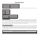
Specifications Heating Specifications Fuel Burn Rate* 1.5 - 5.0 lbs./hr. (0.7 - 2.3 kg/hr) Burn Time (lowest setting) 80 hrs. Hopper Capacity 130lbs. (59kg) * Pellet size may effect the actual rate of fuel feed and burn times. Fuel feed rates may vary by as much as 20%. Use PFI listed fuel for best results. Dimensions Height 34”(864mm) Width 26”(660mm) Depth 26”(686mm) Weight 210 lbs. (95.5kg) Electrical Specifications Electrical Rating 110-120 volts, 60 HZ, 3.
Installation INSTALLATION OPTIONS Read this entire manual before you install and use your pellet stove. Failure to follow instructions may result in property damage, bodily injury, or even death, see specific installation details for clearances and other installation requirements. Freestanding Unit - supported by pedestal/legs and placed on a non-combustible floor surface in compliance with clearance requirements for a freestanding stove installation.
VENTING REQUIREMENTS • INSTALL VENT AT CLEARANCES SPECIFIED BY THE VENT MANUFACTURER. • DO NOT CONNECT THE PELLET VENT TO A VENT SERVING ANY OTHER APPLIANCE OR STOVE. • DO NOT INSTALL A FLUE DAMPER IN THE EXHAUST VENTING SYSTEM OF THIS UNIT. The following installation guidelines must be followed to ensure conformity with both the safety listing of this stove and to local building codes. Do not use makeshift methods or compromise in the installation.
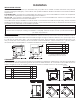
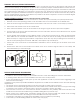
VENT TERMINATION CLEARANCES A. Minimum 4-foot (1.22m) clearance below or beside any door or window that opens. B. Minimum 1-foot (0.3m) clearance above any door or window that opens. C. Minimum 3-foot (0.91m) clearance from any adjacent building. G D. Minimum 7-foot (2.13m) clearance from any grade when adjacent to public walkways. E. Minimum 2-foot (0.61m) clearance above any grass, plants, or other combustible materials. F. Vent Termination Clearances Minimum 3-foot (0.
THROUGH THE ROOF/CEILING INSTALLATION When venting the heater through the ceiling, the pipe is connected the same as through the wall, except the clean-out tee is always on the inside of the house, and a 3”(76mm) adapter is added before the clean-out tee. You must use the proper ceiling support flanges and roof flashing (supplied by the pipe manufacturer; follow the pipe manufacturer’s directions). It is important to note that if your vertical run of pipe is more than 15ft (4.
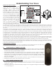
Understanding Your Stove 4 HOW YOUR STOVE WORKS 3 4 Digit Display Your pellet stove utilizes a inclined auger fuel feed system that is operated by a microprocessor controlled digital circuit board. The digital circuit board allows the Up / Down Buttons : inclined auger fuel feed system to Heat Range run in a timer-based, non-continuous Room Fan Auto Mode cycle; this cycling allows the auger Draft Fan Indicator to run for a predetermined period of seconds.
Control Panel Overview Turning the heater “On/Off”, as well as adjustments for the fuel feed rate and room fan speed are performed by pressing the appropriate button(s) on the control panel which is located on the lower left-hand side of your heater. ON/OFF Pressing the “On” button on the control panel will begin the start-up sequence for the heater. Fuel will begin to feed through the auger feed system then ignite after approximately 5 minutes.
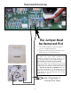
Thermostat Hook-Up The Jumper Must Be Removed First 1. Put female terminals on the lead wires to your low voltage thermostat. 2. Plug one thermostat lead onto each of the terminal posts on the circuit board. IMPORTANT NOTE: The purpose of the T’Stat is to make the stove cycle between the preselected desired heat range setting (”1” to “5”) and the minimum heat range setting of “1”. The T’Stat will not turn the stove on and off.
UNIT PREPARATION Operation After carefully unpacking and reading the instructions for installing your stove, you will need to perform the following steps: • Attach the included spring handle to the door handle by screwing it on in a respective location. • Attach the electrical cord to the back of the stove first; then plug it into a 110-volt outlet (an outlet surge protector is highly recommended).
6. The Room Fan will not operate at this time since the unit must reach a factory preset temperature. Do not open the viewing door, the auto-start igniter will get very hot during this test. The stove will automatically shut down after approximately 23 minutes. • DO NOT USE CHEMICALS OR FLUIDS TO START THE FIRE - Never use gasoline, gasoline-type lantern fuel, kerosene, charcoal lighter fluid, or similar liquids to start or “freshen up” a fire in this stove.
exhaust blower will continue to operate. When the internal temperature of the unit drops below the factory preset temperature, the distribution blower and exhaust blower will cease to operate. The red light will then shut off and the unit will be completely shut down. The hotter the unit is during its operation, the longer it will take for the stove to complete the shut down cycle.
Fly Ash – This accumulates in the horizontal portion of an exhaust run. Though non-combustible, it may impede the normal exhaust flow. It should therefore be periodically removed. Inspection and Removal – The chimney connector and chimney should be inspected annually or per ton to determine if a creosote or fly ash build-up has occurred. If creosote has accumulated, it should be removed to reduce the risk of a chimney fire. Inspect the system at the stove connection and at the chimney top.
FALL START UP Prior to starting the first fire of the heating season, check the outside area around the exhaust and air intake systems for obstructions. Clean and remove any fly ash from the exhaust venting system. Clean any screens on the exhaust system and on the outside air intake pipe. Turn all of the controls on and make sure that they are working properly. This is also a good time to give the entire stove a good cleaning throughout.
Error Code Error Description Possible Causes Err1 The high limit temperature sensor has tripped. Inadequate ventilation. Room fan failure. Exhaust Blockage. Electrical Open in wiring. Err2 Stove ran out of fuel during normal operation. Hopper Empty. Auger output failure or jam. Flame of fuel quality caused fire to burn too slowly or go out. Electrical Open in wiring.
Wiring Diagram CORRECT WRONG BLACK GRAY Ensure the wires are connected to the bottom two prongs of the hopper switch as shown.
1 2 3 4 5 6 7 8 9 46 48 47 49 Parts Diagram -18-
Parts List Key 1 Part # 69524 Description Feed Door Assembly Qty 42 89586 Nipple 1 1 43 891121 Silicone Hose 3” 2 891372 Door Hinge Pad 2 44 83537 Hose Clamp (#4) 1 3 25080B Feed Door Latch 1 45 88119 Insulation Blanket 1 4 69693 Burnpot Housing Weldment 1 46 88168 Burnpot Housing Gasket 1 5 86624 Burnpot Assembly 1 47 26096MB Hearth 1 6 25513 Ash Cleanout 2 48 26097MB Grill Mount - Left 1 7 69713MB Top/Lid Weldment 1 49 26098MB Grill Mount - Right 1
Notes -20-
Notes -21-
Notes -22-
Service Record It is recommended that your heating system is serviced regularly and that the appropriate Service Interval Record is completed. SERVICE PROVIDER Before completing the appropriate Service Record below, please ensure you have carried out the service as described in the manufacturer’s instructions. Always use the manufacturer's specified spare part when replacement is necessary.
How To Order Repair Parts This manual will help you obtain efficient, dependable service from your heater, and enable you to order repair parts correctly. Keep this manual in a safe place for future reference. When writing, always give the full model number which is on the nameplate attached to the heater. When ordering repair parts, always give the following information as shown in this list: 1. The part number_______________________________________________________________________________ 2.
Enregistrement De Service Il est recommandé que votre système de chauffage est desservi régulièrement et que le Service Interval enregistrement approprié est terminée. FOURNISSEUR DE SERVICES Avant de terminer l’enregistrement de service approprié ci-dessous, s’il vous plaît vous assurer que vous avez effectué le service tel que décrit dans le les instructions du fabricant. Toujours utiliser pièce de rechange indiquée par le fabricant lors de remplacement est nécessaire.
25513 6 86624 5 69693 4 25080B 3 891372 2 69524 1 Réf Clé 7 8 9 10 11 Schéma des pièces La description Montage D'alimentation De Porte Charnière De Porte Pad Nourrissez Loquet De Porte 80491 69787 12 80462 18 80461 17 891132 22 891189 21 80488 28 891169 27 25495 26 891161 25 88117 31 80480 34 80472 38 88118 37 Pot De Qté.
Schéma des pièces 49 48 47 46 9 1 2 3 4 5 6 7 8 -18-
Schéma de câblage SOURCE ÉLECTRIQUE ALLUMEUR MICRORUPTEUR MOTEUR D'ENTRAÎNEMENT DE LA VIS SANS FIN CORRECT BLANC NOIR PCB ALLUMEUR PRESSOSTAT BLANC MARRON MARRON ORANGE BLEU ROUGE BLANC NOIR FAUX PCB PRINCIPAL THERMISTOR GRIS NOIR BLANC BLANC VENTILATEUR D'ÉVACUATION NOIR Assurez-vous que les fils sont connectés aux deux broches inférieures de l’interrupteur de la trémie, comme illustré.
Codes d’erreur et indicateurs d’affichage Code d’erreur Description de l’erreur Causes possibles Moteur du ventilateur de la pièce bloqué ou défectueux. Le fusible de sortie du ventilateur de la pièce a sauté. Err8 Moteur du ventilateur de tirage bloqué ou défectueux. Le fusible de sortie du ventilateur de tirage (ventilateur d’évacuation) a sauté. Err7 Le fusible de sortie de l’igniteur a sauté. Err6 Moteur de la vis sans fin bloqué ou défectueux.
Dépannage • Déconnectez le cordon d'alimentation avant d'effectuer tout travail d'entretien ! REMARQUE: Mettre l'interrupteur ON/OFF (marche/arrêt) sur "OFF" ne coupe pas l'alimentation des composants électriques du poêle. • Ne tentez jamais de réparer ou de remplacer une pièce du poêle à moins que des instructions pour le faire ne soient fournies dans ce manuel. Tous les autres travaux devront être effectués par un technicien qualifié.
DÉTECTEURS DE FUMÉE ET DE CO Le brûlage du bois produit naturellement des émissions de fumée et du monoxyde de carbone (CO). Le CO est un gaz poison lorsque l’exposition se fait à des concentrations élevées pour une période de temps prolongée. Bien que les systèmes de combustion modernes des chauffages réduisent de façon importante la quantité de CO émis par la cheminée, l’exposition aux gaz dans des endroits fermés ou clos peut être dangereuse.
REMARQUE: L’unité s’éteindra également en cas de panne du ventilateur d’aspiration ; si c’est le cas, l’unité ne redémarrera pas et vous devrez contacter le service après-vente au (800) 750-2723. ACCESSOIRES DE SÉCURITÉ ET D’EMBALLAGE Votre poêle à granulés comprend un pressostat de sécurité qui aide à garantir que tout fonctionne normalement avant d’approvisionner le pot de combustion en combustible.
Le chauffage est conçu pour ne brûler que des granulés de classe supérieure PFI. Cet appareil peut aussi brûler des granulés de classe ordinaire après le 16 mai 2015. NE PAS BRÛLER: 9. Fumier ou restes d’animaux; 1. Des ordures; 2. Des déchets de tonte ou résidus de jardin; 10. Bois de grève en eau salée ou autres matériaux précédemment saturés par de l’eau salée; 3. Des matériaux contenant du caoutchouc, incluant les pneus; 11. Bois non séché; ou 4. Matériaux contenant du plastique; 12.
PRÉPARATION DE L’UNITÉ Fonctionnement Après avoir déballé avec précaution et lu les instructions d’installation de votre poêle, vous devrez suivre les étapes suivantes: • Fixez la poignée ressort fournie à la poignée de la porte en la vissant à l’emplacement correspondant. • Raccordez d’abord le cordon électrique au dos du poêle ; puis branchez-le dans une prise de 110 volts (un para sur tenseur de prise de courant est fortement recommandé).
Vue d’ensemble du panneau de contrôle La mise en marche et l’arrêt du système de chauffage, ainsi que les réglages du taux d’approvisionnement en combustible et de la vitesse du ventilateur de la pièce sont réalisés en appuyant sur le(s) bouton(s) approprié(s) du panneau de contrôle qui se trouve(nt) sur le côté inférieur gauche de votre système de chauffage. Cette unité peut basculer entre un fonctionnement automatique ou un fonctionnement manuel. Le régulateur fonctionne par défaut en mode automatique.
Raccordement Du Thermostat Le cavalier doit être enlevé en premier 1. Placez les bornes femelles sur les fils conducteurs de votre thermostat basse tension. 2. Branchez un fil de thermostat sur chacun des bornes du circuit imprimé. REMARQUE IMPORTANTE: L’objet du T’Stat est de faire en sorte que le poêle se programme entre le réglage présélectionné de la plage de chaleur désirée («1» à «5») et le réglage de la plage de chaleur minimale de «1». Le T’Stat n’allumera ni ne éteindra le poêle.
Comprendre votre poêle 4 3 COMMENT FONCTIONNE VOTRE POÊLE Afficheur à 4 chiffres Votre poêle à granulés utilise un système d'alimentation du combustible à vis sans fin B inclinée qui est commandé par un circuit imprimé numérique contrôlé par microprocesseur.
INSTALLATION À TRAVERS LE TOIT/PLAFOND Lors de l'aération du poêle à travers le plafond, le tuyau est raccordé de la même façon qu'à travers la paroi, à l'exception du raccord en T du regard qui est toujours à l'intérieur de la maison, et un adaptateur de 3 pouces (76mm) est ajouté avant le T du regard. Vous devez utiliser les platines supports appropriées du plafond et le chaperon de toiture (fournis par le fabricant de tuyaux ; respectez les indications du fabricant de tuyaux).
DÉGAGEMENTS DE L'ÉVACUATION DE TIRAGE A. B. C. D. E. F. G. H. I. Dégagement minimum de 4 pieds (1,22m) sous et à côté d'une porte ou d'une fenêtre qui s'ouvre. Dégagement minimum d'1 pied (0,3m) au-dessus d'une porte ou d'une fenêtre qui s'ouvre. Dégagement minimum de 3 pieds (0,91m) à partir de toute construction adjacente. Dégagement minimum de 7 pieds (2,13m) de tout passage lorsqu'il est adjacent à des allées publiques.
EXIGENCES DE VENTILATION • Installez la ventilation avec les dégagements indiqués par le fabricant du système de ventilation. • Ne raccordez pas la ventilation des granulés à une ventilation utilisée par un autre appareil ou poêle. • N'installez pas un registre de carneau dans le système de ventilation d'évacuation de cette unité. Les instructions d'installation suivantes doivent être respectées pour assurer la conformité avec la liste de sécurité de ce poêle et les codes locaux de construction.
OPTIONS D’INSTALLATION Installation Lisez l’intégralité de ce manuel avant d’installer et d’utiliser votre poêle à granulés. Le non-respect des instructions peut entraîner des dommages matériels, des blessures corporelles ou même la mort, voir les détails d’installation spécifiques pour les dégagements et autres exigences d’installation.
Spécifications Heating Specifications 130lbs. (59kg) Capacité de la trémie 80 hrs. Temps de combustion (réglage le plus bas) 1,5 - 5 lbs./hr. (0,7 - 2,3 kg/hr) Vitesse de combustion du combustible* * La taille des granulés peut affecter le taux réel d’approvisionnement en combustible et les durées de combustion. Les taux d’approvisionnement en combustible peuvent varier jusqu’à 20%. Utilisez les combustibles agréés PFI pour de meilleurs résultats. Dimensions 1,210 lbs.
• • • • • • • • • • • • • • • • • • Précautions de sécurité IMPORTANT: Lisez entièrement ce manuel avant d'installer et d'utiliser ce produit. Ne pas le faire peut entraîner des dommages matériels, des blessures personnelles voire la mort. L'installation correcte de ce poêle est primordiale pour un fonctionnement efficace en toute sécurité. Installez la ventilation avec les dégagements indiqués par le fabricant du système de ventilation.
MODÈLE: AP130 CONSERVEZ CES INSTRUCTIONS. CE MANUEL VOUS AIDERA À OBTENIR UN SERVICE EFFICACE ET FIABLE À PARTIR DU RADIATEUR ET VOUS PERMETTRA DE COMMANDER CORRECTEMENT LES PIÈCES DE RÉPARATION. GARDEZ DANS UN ENDROIT SÛR POUR RÉFÉRENCE FUTURE. • Veuillez lire entièrement ce manuel d’installation et d’utilisation AVANT de mettre en place et de faire fonctionner votre nouveau poêle à granulés de bois pour chauffage de pièce.