DPX-100 Graphic Equalizer Compressor/Limiter Operating Manual 25 Model DPX-100 Graphic Equalizer Compressor/Limiter 40 63 100 180 250 400 630 1K 1.8K 2.5K 4K Gain 16K 6.3K 10K +6 +4 +2 0 -3 -9 +15 +10 +5 0 -5 -10 -15 -∞ dB Th. 2 Range ±6dB ±15dB HPF -3 In Out -10 -15 -6 +3 +6 -6 EQ Sig Clip 20Hz Out 0 +10 dB +15 Gain -10 -3 4 Clip Input/Output Level (dB) -18 -15 -12 -9 -6 -3 0 +3 +6 +9 +20 Gain Reduction (dB) 6 8 10 12 14 16 18 20 0 +3 5 7 +6 3 +10 +20 2.
Operating Manual - DPX-100 Graphic Equalizer - Compressor/Limiter Table Of Contents 2 1 INTRODUCTION . . . . . . . . . . . . . . . . . . . . . . . . . . . . . . . . . . . . . . . . . . . . . . . . . . . . . . . 3 2 UNPACKING . . . . . . . . . . . . . . . . . . . . . . . . . . . . . . . . . . . . . . . . . . . . . . . . . . . . . . . . . . . . 3 3 AC POWER REQUIREMENTS . . . . . . . . . . . . . . . . . . . . . . . . . . . . . . . . . . . . . . . . . . . 3 4 MECHANICAL INSTALLATION . . . . . . . . .
Operating Manual - DPX-100 Graphic Equalizer - Compressor/Limiter The lightning flash with arrowhead symbol, within an equilateral triangle, is intended to alert the user to the presence of uninsulated "dangerous volt age" within the product's enclosure that may be of sufficient magnitude to constitute a risk of electric shock to persons.
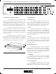
Operating Manual - DPX-100 Graphic Equalizer - Compressor/Limiter 25 40 63 1 00 1 80 2 50 4 00 6 30 1K 1 .8 K 2 .5 K 4K 1 6K 6 .3 K Gain 1 0K +1 5 +1 0 +5 0 M o del D PX -10 0 Graphic E q ualizer Com pres so r/L imiter -5 -1 0 +6 +4 +2 Range 0 -3 -9 HPF -∞ -1 5 dB ± 6 dB ±1 5d B S ig C lip 2 0 Hz O ut 4. MECHANICAL INSTALLATION 5. EQ CONTROLS The DPX-100 mounts in a standard 19 inch equipment rack.
Operating Manual - DPX-100 Graphic Equalizer - Compressor/Limiter Th. 0 -3 -6 +3 +6 -6 -1 0 +1 0 -1 5 dB +1 5 Gain -1 0 -2 0 -4 0 2 -3 C lip Inpu t/ O utpu t L evel (dB ) -1 8 -1 5 -1 2 -9 -6 -3 0 +3 +6 +9 +20 G ain R e ductio n (d B) 6 8 10 12 14 16 18 20 4 0 +3 5 3 +6 +1 0 + 2 0 2 .5 2 dB +22 Threshold 7 10 ∞ Ratio 2 3 .5 5 1 .5 -6 10 20 1 3 0 .5 2 mS 20 Attack .1 S e c 3 Release +3 O utpu t Inpu t +6 -1 0 15 .2 0 -3 1 .
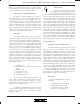
Operating Manual - DPX-100 Graphic Equalizer - Compressor/Limiter Comp INPUT S ar e Active B a la n c e d . O UTPUT S M a y B e Wir e d B a la n c e d O r Un ba la n c e d . AC Model DPX-100 Made In USA T IP = D e t e c (Use M R ING 3 2 1 X LR Fe m a le S h o wn CAUTION 1 00 -1 2 0VAC 5 0-60 Hz 1 2W R isk o f Elec tric S hock. D o Not Open the double time constant, release from gain reduction after a brief transient is always fast, with a slower release after a sustained overdrive. 6.
Operating Manual - DPX-100 Graphic Equalizer - Compressor/Limiter mpressor/Limiter Graphic Equalizer PUSH PUSH t e c to r R e tu rn / D u ckin g In p u t Mono Plug For Ducking) ING = D e t e c to r S e n d Chain In O ut Input D e te ctor Output Input 7.2 Inputs and Outputs 7.3 Chain The DPX-100 uses two different audio connector types. 1/4" TRS (tip-ring-sleeve) phone jacks, and three pin XLR connectors will allow interfacing to most professional audio products.
Operating Manual - DPX-100 Graphic Equalizer - Compressor/Limiter equalizer effectively, you need to translate your idea of the tone you want to produce into a range of numerical frequencies. This is simple after a little practise. Here are a few references which are useful for starting points: - Very low bass (the “wind” in a kick drum, almost felt as much as heard -40Hz-80Hz.
Operating Manual - DPX-100 Graphic Equalizer - Compressor/Limiter if this type of transient doesn’t destroy a speaker outright, it may damage the speaker surround in such a way as to cause mechanical abrasion and future failure. Alternatives For Sound Installations To install a compressor/limiter in a sound system using a passive crossover, insert it between your mixing console output and the power amplifier input. For systems using electronic crossovers, there are two ways to use a compressor/limiter.
Operating Manual - DPX-100 Graphic Equalizer - Compressor/Limiter e. Attack time to 5mS. f. Release time to 1 Sec. g. Limit switch IN 2. Using a 1/3 octave (31 band) or parametric equalizer, set the EQ controls to a flat setting, and if the equalizer has an overall volume control, boost it by 10 to 15 dB. 3. Open up several microphone input channels to a normal operating level, with typical EQ settings, and turn the console master fader up to a louder than normal setting.
Operating Manual - DPX-100 Graphic Equalizer - Compressor/Limiter 9. DESIGN THEORY Graphic Equalizers: The Basics While most graphic equalizers look very much the same, there are several important differences in the circuitry used to implement various designs. Perhaps the major differences are in the filters. Some equalizers use a filter made of a capacitor, an inductor, and a resistor, or “RLC” filter. The advantage here is simplicity, but the real disadvantage is the inductor itself.
Operating Manual - DPX-100 Graphic Equalizer - Compressor/Limiter out of an audio system, you have to keep your standard operating level as high as possible without risking distortion. GAIN RIDING One solution to the noise vs. distortion trade-off is to keep your hand on the level control and manually adjust gain to suit the program. Indeed, there are times when this approach is entirely satisfactory.
Operating Manual - DPX-100 Graphic Equalizer - Compressor/Limiter signal before the gain control FET and then amplify it again. Of course this results in less than ideal noise performance and imposes a frustrating trade-off: less noise = more distortion. A number of VCA’s based on the exponential voltage-current characteristic of a bipolar junction transistor have been used. One of the most common is called a “transconductance amplifier”.
Operating Manual - DPX-100 Graphic Equalizer - Compressor/Limiter 10. BLOCK DIAGRAM Distorted Sound SIG 2 1 CLIP 3 6dB/15dB EQ INPUT GAIN 15 BAND EQ HPF Excessive Hum or Noise 2 3 1 + HPF In/Out EQ In/Out EQ OUTPUT CHAIN 2 1 3 This will only be caused by too much signal which will show on the Clip LED. If the LED is not flashing, there is an overload somewhere else in the signal path. Adjust the relative gain of each component in your chain to keep everything at a comfortable level.
Operating Manual - DPX-100 Graphic Equalizer - Compressor/Limiter When Using Heavy Compression, Background Noise Is Noticeable During Quiet Sections Of The Program As defined in the section on compression, quiet program material is effectively made louder while loud peaks are made quieter. When the program source is thus raised in volume, its noise floor is also raised in volume by a proportionate amount.
Operating Manual - DPX-100 Graphic Equalizer - Compressor/Limiter 14. DIMENSIONS 1 7 .0 0 6 .0 0 0 .1 0 1 .2 5 1 .7 5 0 .
2 3 4 DETECTOR 6 GAIN +/- 15db C5 R11 68 D1 1N4148 VR1 B10K 3 7 1 15K 45P2000 47U U18 R10 7 52P2150 Ec+ IN R3 J1 10.0K D U1B 5 7 4560 6 3 27P 1 47P1295 4560 2 C6 D6 27P R37 12K 3 1 VR4 A1MEG R33 1K 100K 47K 1N4148 D15 D4 -18 1N4148 GAIN METER VR3 R28 A10K 100 R30 68K 1.5U R32 1K C80 1N0754 U4B D2 6 Q1 2N4125 7 4560 5 1.5U R31 3.
2 3 4 C17 R71 C18 TO ODD E .1u .1u T2 63.4K 5 C26 U10B 6 R91 VR9 63.4K R70 7 4560 5 R69 JP25 4.7K TO EVEN .1u JP25/2 .1u R90 39.2K VR10 3 C34 U10A 2 1 4560 R89 JP26 4.7K TO ODD .1u JP26/2 R110 25.5K C42 7 4560 5 R109 JP27 TO EVEN .1u 4.7K R93 10.0K R130 15.8K VR12 U11A 2 1 4560 3 JP28 R129 E 4.7K JP27/2 JP28/2 R132 7.87K T2 R113 10.0K 40 Hz T3 15.8K R112 7.87K T1 25 Hz VR11 U11B 6 .1u R131 T2 25.5K R92 7.87K C41 .
1 2 3 4 5 6 8 7 OUTPUT LEVEL (db) GAIN REDUCTION (db) D43 D42 D41 -2(R) -4(R) -6(R) -8(R) -10(R) -12(R) -14(R) -16(R) -18(R) -20(R) PEAK BUS 1 R149 R148 2.4K 390K C52 .1U -18 J14/2A 5 J14A GAIN METER 4 +18 J14C J14/2C +18 -18 J14D J14/2D -18 R162 4.
Operating Manual - DPX-100 Graphic Equalizer - Compressor/Limiter ASHLY AUDIO INC. 847 Holt Road Webster, NY 14580-9103 Phone: (585) 872-0010 Fax: (585 872-0739 Toll Free (800) 828-6308 Internet: www.ashly.com 2002 by Ashly Audio Corporation. All rights reserved worldwide.