ION 3D Series User Manual Version 1.0 Published September 2010 Copyright©2010 ASRock INC. All rights reserved.
Copyright Notice: No part of this manual may be reproduced, transcribed, transmitted, or translated in any language, in any form or by any means, except duplication of documentation by the purchaser for backup purpose, without written consent of ASRock Inc. Products and corporate names appearing in this manual may or may not be registered trademarks or copyrights of their respective companies, and are used only for identification or explanation and to the owners’ benefit, without intent to infringe.
Safety instructions Your system is designed and tested to meet the latest standards of safety for information technology equipment. However, to ensure your safety, it is important that you read the following safety instructions. Setting up your system • • • • • • Read and follow all instructions in the documentation before you operate your system. Do not use this product near water or a heated source such as a radiator. Set up the system on a stable surface. Openings on the chassis are for ventilation.
Safety cautions and warnings Optical Drive Safety Information Optical drives sold with this system contains a CLASS 1 LASER PRODUCT. CAUTION: Invisible laser radiation when open. Do not stare into beam or view directly with optical instruments. WARNING: Making adjustments or performing procedures other than those specified in the user’s manual may result in hazardous laser exposure. Do not attempt to disassemble the optical drive.
Contents 1 Introduction ................................................... 7 1.1 1.2 1.3 1.4 1.5 1.6 2 3 4 5 Package Contents .......................................................... Specifications ................................................................ System Motherboard Components ............................... Rear Panel Connections ................................................ System Chassis ............................................................. Remote Controller ...............
.5 Hardware Health Event Monitoring Screen .................. 6.6 Boot Screen ................................................................... 6.6.1 Boot Settings Configuration .................................. 6.7 Security Screen ............................................................ 6.8 Exit Screen .................................................................... 44 44 45 46 47 7 Software Support ........................................... 48 7.1 Install Operating System ..................
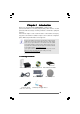
Chapter 1 Introduction Thank you for purchasing ASRock ION 3D Series, a reliable product produced under ASRock’s consistently stringent quality control. It delivers excellent performance with robust design conforming to ASRock’s commitment to quality and endurance. In this manual, chapter 1 and 2 contain introduction of the hardware and step-bystep guide to the hardware installation. Chapter 3 and 4 contain the configuration guide to BIOS setup and information of the Support CD.
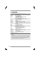
1.2 * Specifications For barebone system, it may not contain memory, HDD or ODD. Processor Support Intel® Atom TM D525 Dual Core Processor Chipset Intel® ICH8M chipset Memory Support DDR2 800MHz, 2 x SO-DIMM slots, maximun up to 4GB VGA NVIDIA® GT218-ION Graphics (with 512MB DDR3 Frame buffer memory) Storage Support 2.5” SATA HDD LAN Gigabit LAN Front I/O 2 x USB 3.0, 1 x MIC, 1 x Head phone Rear I/O 1 x HDMI, 1 x DVI (Dual-Link), 1 x D-Sub VGA, 6 x USB 2.0, 1 x S/PDIF Audio 7.
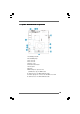
1.3 System Motherboard Components 1. Southbridge heatsink 2. Clear CMOS jumper 3. Fan connector 4. Fan connector 5. Memory socket 6. Infrared module header 7. CPU heatsink 8. CPU Fan 9. Mini-PCI Express expansion slot: (USB interface only) For WiFi module 10. SATA connector: For ODD SATA data cable 11. ATX5V output power connector for slim ODD & 2.5” HDD 12.
NOTE. 1. SATA and Power Connections Connect to ODD SATA & Power Connections HDD ODD Connect to HDD Connect to SATA Connector (10) Connect to ATX5V Power Connector (11) Connect to SATA Connector (12) 2.
1.4 Rear Panel Connectinos 13. DC-In jack 14. Optical S/PDIF Out port 15. Mic In (Pink): Microphone 16. Front L/R Out (Lime): Stereo speakers or headphones 17. HDMI connector 18. Display (VGA) port 19. DVI connector (dual-link) 20. USB2.0 ports: USB devices 21. LAN (RJ-45) port: Local Area Network 22. Line In (Blue) for 2/4/6 channel; Rear (Blue) for 8 channel 23. Center/LFE (Orange): Center / subwoofer speakers 24.
1.5 System Chassis Opening the system chassis 1. Remove the screws on the backside. 2. Slide the top panel backwards. 25. Optical Disc Drive 26. Power ON/OFF button with status indicator 27. Drive activity indicator 28. Headphone 29. Microphone 30. USB3.
1.6 Remote Controller Some remote controller functions listed above are only available with the relative hardware equipments. If the hardware equipments you adopt are not compatible with the system, you are not allowed to use these functions. This product is designed to meet MCE standards.
Chapter 2 System Quick Installation 1. Connecting USB Devices (USB2.0 Ports) 2. Connecting VGA Monitor (Display (VGA) Port) 3. Connecting the Network (LAN (RJ-45) Port) 4.
5. Connecting DVI Device (DVI Port) 6. Connecting External Audio Device (Line In Port for 2/4/6 Channel; Rear Port for 8 Channel) 7. Connecting Stereo Speakers or Headphones (Front L/R Out Port) 8.
9. Connecting Center / Subwoofer Speakers (Center/LEF Port) 10. Connecting Side Speakers (Side Port for 4/6/8 Channel) 11. Connecting Optical Device (Optical S/PDIF Out Port) 12.
13. Power on the System (Power Switch) 14. Connecting Headphone / Microphone / USB3.
Chapter 3 Reinstalling System Components 1. Remove the cover screws on the rear panel. Note: For safety reasons, please ensure that the power cord is disconnected before opening the case. 2. Slide the side cover toward the rear panel and pull the side cover upwards. 3. To change the storage drives, you need to remove SATA and power cables from ODD / HDD first, and unscrew the screws from both side. 4. Pull ODD / HDD rack backwards and take it out from the bay.
5. Unscrew the screws from the side of ODD / HDD rack, and change your required ODD / HDD. 6. Refer to above steps to place the new ODD / HDD to the chassis. Replace the side cover and fasten the screws.
Chapter 4 Driver Installation To install the drivers to your system, please insert the support CD to your optical drive first. Then, the drivers compatible to your system can be auto-detected and listed on the support CD driver page. Please follow the order from up to bottom side to install those required drivers. Therefore, the drivers you install can work properly.
Chapter 5 Utility Menu The utilities meu shows the applications and other software that this product supports. 5.1 Instant Boot 5.1.1 Introduction Instant Boot, a user-friendly tool that allows you to turn on your PC in just a few seconds, provides a much more efficient way to save energy, time, money, and improves system running speed for your system *. It is applicable to Windows® 7 / 7 64-bit / Vista™ / Vista™ 64-bit / XP / XP 64-bit.
5.1.2 Installation Please read below procedures carefully before you install Instant Boot. A. Install Instant Boot driver from ASRock support CD, or you may click following link to get the latest utility and BIOS: http://www.asrock.com/feature/InstantBoot/download.asp B. Execute the Instant Boot installation program under Windows®. Please follow the instructions on Instant Boot setup page. a. Click “Next” to continue. b. Select destination location.
d. Click “Install” to begin installing Instant Boot driver. e. Click “Finish” to complete and exit the setup. C. After the installation is completed, you will find an ASRock Instant Boot icon on the Windows® desktop. D. Double click ASRock Instant Boot icon on the desktop, then Instant Boot main menu will pop up. E. On Instant Boot main menu, you can choose “Fast Mode”, “Regular Mode” or “Disable Instant Boot”. After that, please click “Apply” to save the change.
H. Next time when you turn on your system, you can enjoy the benefit of Instant Boot. 5.2 ASR ock OC TTuner uner ASRock 5.2.1 Introduction ASRock OC Tuner is a user-friendly overclocking tool which allows you to guard your system by hardware monitor function and overclock your hardware devices to get the best system performance. There are 3 major sections that are easy to fine-tune and monitor: Overclocking, Voltage Control, and Hardware Monitor.
b. Select destination location. You may choose a different folder if you need, and click “Next”. c. Select the start menu folder. You may choose a different folder if you need, and click “Next”. d. Click “Install” to begin installing ASRock OC Tuner driver. e. Click “Finish” to complete and exit the setup.
C. After the installation is completed, you will find an ASRock OC Tuner icon on the Windows® desktop. D. Double click ASRock OC Tuner icon on the desktop, then ASRock OC Tuner main menu will pop up. Auto apply when program starts If you check this button, it will save your settings when you close OC Tuner window. And next time when you run OC Tuner, it will start with the settings you made. If you do not check this button, next time when you run OC tuner, it will start with the default settings.
System Health – In the System Health section, there are two major chapters: System Health and CPU Quiet Fan. Under the System Health chapter, it shows the major readings of CPU, chipset and GPU Temperature. You may find out if there’s any abnormal situation occurs to your system’s temperature. Under the CPU Quiet Fan chapter, the Chassis Fan Speed will show the default settings of your system. You are able to adjust the setting too by clicking the “Up/Down” arrows and confirm by “Go” afterward.
5.3 CyberLink D VD Suite free bundle (T rial version DVD (Trial version,, including PowerDVD, PowerDirector, etc) CyberLink DVD Suite includes five softwares: PowerDVD, PowerBackup, PowerDirector, Power2Go and MediaShow. Please read below description for details. PowerDVD World-renowned and award-winning PowerDVD delivers the ultimate DVD and high-definition movie experience on the PC. Feature-rich nevigation controls enhance and personalize the movie experience.
PowerDirector CyberLink PowerDirector provides cool features to ensure editing movies is fun and fast! Whether you are an advanced or entry-level video editor, PowerDirector lets you enhance your camcorder videos and produce professional home movies. PowerDirector offers a dual mode editing interface, comprehensive production tools, technologies that save time and maintain your video quality, and a built-in CD/DVD authoring program.
5.4 Symantec Norton AntiVirus Software free bundle (Trial (T rial version) Protect your PC with Norton Internet Security, the fastest virus, spyware, Internet protection. Norton Internet Security can stop online identity theft, viruses, spyware, bots and more, stop attacks before they get on your PC, deliver clear threat and performance explanations, identify unsafe web sites right in your search results, and use intelligence-driven Norton Insight Network for faster, fewer, shorter scans.
5.5 ASRock AIWI Utility To experience intuitive motion controlled games is no longer only available at Wii. ASRock AIWI utility introduces a new way of PC gaming operation. ASRock AIWI is the world's first utility to turn your iPhone/iPod touch as a game joystick to control your PC games.
5.6 The best Apple charge companion - ASRock APP Charger Fast Charge & Charge Anytime! If you desire a faster, less restricted way of charging your Apple devices, such as iPhone/iPod/iPad Touch, ASRock has prepared a wonderful solution for you ¡V ASRock App Charger. Simply installing the App Charger driver, it makes your iPhone charged much quickly from your computer and up to 40% faster than before*.
Chapter 6 BIOS SETUP UTILITY 6.1 Introduction This section explains how to use the BIOS SETUP UTILITY to configure your system. The BIOS chip on the system stores the BIOS SETUP UTILITY. You may run the BIOS SETUP UTILITY when you start up the computer. Please press or during the Power-On-Self-Test (POST) to enter the BIOS SETUP UTILITY, otherwise, POST will continue with its test routines.
6.1.2 Navigation Keys Please check the following table for the function description of each navigation key.
6.3 OC TTweak weak er Screen weaker In the OC Tweaker screen, you can set up overclocking features.
DRAM Frequency If [Auto] is selected, the motherboard will detect the memory module(s) inserted and assigns appropriate frequency automatically. You may select [Auto], [333MHz DDR2_667)] or [400MHz DDR2_800)]. DRAM Timing Control Use this item to control DRAM Timing.
DRAM tRRD This controls the number of DRAM clocks for TRRD. Configuration options: Configuration options: [Auto], [2] to [15]. DRAM tRTP This controls the number of DRAM clocks for TRTP. Configuration options: [Auto], [2] to [13]. CPU Voltage Use this to select CPU Voltage. Configuration options: [Auto], [1.10V] to [1.25V]. The default value is [Auto]. DRAM Voltage Use this to select DRAM Voltage. Configuration options: [Auto], [1.80V] to [2.20V]. The default value is [Auto]. +1.
6.4 Advanced Screen In this section, you may set the configurations for the following items: CPU Configuration, Chipset Configuration, ACPI Configuration, Storage Configuration and USB Configuration. Main BIOS SETUP UTILITY Boot OC Tweaker Advanced H/W Monitor Advanced Settings Security Exit Options for CPU WARNING : Setting wrong values in below sections may cause system to malfunction.
6.4.1 CPU Configuration BIOS SETUP UTILITY Advanced CPU Configuration CPU Thermal Throttling Execute-Disable Bit Capability Hyper Threading Technology [Enabled] [Enabled] [Enabled] Enter to enable or disable P4 CPU internal thermal control mechanism. +F1 F9 F10 ESC Select Screen Select Item Change Option General Help Load Defaults Save and Exit Exit v02.54 (C) Copyright 1985-2005, American Megatrends, Inc.
6.4.2 Chipset Configuration BIOS SETUP UTILITY Advanced Chipset Settings Onboard HD Audio OnBoard Lan WiFi Radio [Enabled] [Enabled] [Enabled] +F1 F9 F10 ESC Select Screen Select Item Change Option General Help Load Defaults Save and Exit Exit v02.54 (C) Copyright 1985-2005, American Megatrends, Inc. Onboard HD Audio This allows you to enable or disable the onboard HD Audio feature. OnBoard Lan This allows you to enable or disable the onboard Lan feature.
6.4.3 ACPI Configuration BIOS SETUP UTILITY Advanced ACPI Configuration Suspend To RAM Check Ready Bit [Auto] [Enabled] PCI Devices Power On RTC Alarm Power On [Disabled] [By OS] ACPI HPET Table [Enabled] Select auto-detect or disable the STR feature. +F1 F9 F10 ESC Select Screen Select Item Change Option General Help Load Defaults Save and Exit Exit v02.54 (C) Copyright 1985-2005, American Megatrends, Inc.
6.4.4 SA SATTA Configuration BIOS SETUP UTILITY Advanced Options Storage Configuration [IDE] Configure SATA as IDE AHCI [Not Detected] [Not Detected] SATAII_1 SATAII_2 +F1 F9 F10 ESC Select Screen Select Item Change Option General Help Load Defaults Save and Exit Exit v02.54 (C) Copyright 1985-2003, American Megatrends, Inc. Configure SATA as Use this item to configure SATA mode. The default value of this option is [IDE]. Configuration options: [IDE] and [AHCI].
6.4.6 USB Configuration BIOS SETUP UTILITY Advanced USB Configuration USB 2.0 Support Legacy USB Support USB 3.0 Controller [Enabled] [Enabled] [Enabled] To enable or disable the onboard USB controllers. USB Keyboard/Remote Power On [Disabled] [Disabled] USB Mouse Power On +F1 F9 F10 ESC Select Screen Select Item Change Option General Help Load Defaults Save and Exit Exit v02.54 (C) Copyright 1985-2005, American Megatrends, Inc. USB 2.0 Support Use this item to enable or disable the USB 2.0 support.
6.5 Hardware Health Event Monitoring Screen In this section, it allows you to monitor the status of the fan speed. Main OC Tweaker BIOS SETUP UTILITY Advanced H/W Monitor Boot Security Exit Hardware Health Event Monitoring CPU Temperature M/B Temperature : 37 C / 98 F : 31 C / 87 F CPU Fan Speed Chassis Fan Speed : N/A : N/A Vcore + 3.30V + 5.00V : 1.152V : 3.312V : 5.
6.6.1 Boot Settings Configuration BIOS SETUP UTILITY Boot Boot Settings Configuration Full Screen Logo Boot From Onboard LAN Bootup Num-Lock [Enabled] [Disabled] [On] Disabled: Displays normal POST messages. Enabled: Displays OEM Logo instead of POST messages. +F1 F9 F10 ESC Select Screen Select Item Change Option General Help Load Defaults Save and Exit Exit v02.54 (C) Copyright 1985-2003, American Megatrends, Inc. Full Screen Logo Use this item to enable or disable OEM Logo.
6.7 Security Screen In this section, you may set or change the supervisor/user password for the system. For the user password, you may also clear it. Main BIOS SETUP UTILITY OC Tweaker Advanced H/W Monitor Boot Security Settings Security Exit Install or Change the password. Supervisor Password : Not Installed User Password : Not Installed Change Supervisor Password Change User Password Enter F1 F9 F10 ESC Select Screen Select Item Change General Help Load Defaults Save and Exit Exit v02.
6.8 Exit Screen Main OC Tweaker BIOS SETUP UTILITY Advanced H/W Monitor Boot Exit Options Save Changes and Exit Discard Changes and Exit Discard Changes Load Load Load Load Security Exit Exit system setup after saving the changes. F10 key can be used for this operation. BIOS Defaults Performance Setup Default (IDE/SATA) Performance Setup AHCI Mode Power Saving Setup Default Enter F1 F9 F10 ESC Select Screen Select Item Go to Sub Screen General Help Load Defaults Save and Exit Exit v02.
Chapter 7 Software Support 7 . 1 Install Operating System This system supports various Microsoft® Windows® operating systems: 7 / 7 64-bit / VistaTM / VistaTM 64-bit / XP / XP 64-bit. Refer to your OS documentation for more information. 7 . 2 Support CD Information The Support CD contains necessary drivers and useful utilities that enhance the system features. 7 . 2 . 1 Running The Support CD To begin using the support CD, insert the CD into your CD-ROM drive.