Version 1.0 Published July 2020 Copyright©2020 ASRock INC. All rights reserved. Copyright Notice: No part of this documentation may be reproduced, transcribed, transmitted, or translated in any language, in any form or by any means, except duplication of documentation by the purchaser for backup purpose, without written consent of ASRock Inc.
AUSTRALIA ONLY Our goods come with guarantees that cannot be excluded under the Australian Consumer Law. You are entitled to a replacement or refund for a major failure and compensation for any other reasonably foreseeable loss or damage caused by our goods. You are also entitled to have the goods repaired or replaced if the goods fail to be of acceptable quality and the failure does not amount to a major failure. If you require assistance please call ASRock Tel : +886-2-28965588 ext.
Contents Chapter 1 Introduction 1 1.1 Package Contents 1 1.2 Specifications 2 1.3 Motherboard Layout 6 1.4 I/O Panel 9 Chapter 2 Installation 11 2.1 Installing the CPU 12 2.2 Installing the CPU Fan and Heatsink 14 2.3 Installing Memory Modules (DIMM) 22 2.4 Expansion Slots (PCI Express Slots) 24 2.5 Jumpers Setup 25 2.6 Onboard Headers and Connectors 26 2.7 M.2_SSD (NGFF) Module Installation Guide 30 Chapter 3 Software and Utilities Operation 34 3.
3.3.3 BIOS & Drivers 42 3.3.4 Setting 43 Chapter 4 UEFI SETUP UTILITY 44 4.1 Introduction 44 4.1.1 UEFI Menu Bar 44 4.1.2 Navigation Keys 45 4.2 Main Screen 46 4.3 OC Tweaker Screen 47 4.4 Advanced Screen 50 4.4.1 CPU Configuration 51 4.4.2 Onboard Devices Configuration 52 4.4.3 Storage Configuration 54 4.4.4 ACPI Configuration 55 4.4.5 Super IO Configuration 56 4.4.6 Trusted Computing 57 4.4.7 AMD PBS 58 4.4.8 AMD Overclocking 59 4.4.9 AMD CBS 60 4.5 Tools 61 4.
A520M-HDV A520M-HVS Chapter 1 Introduction Thank you for purchasing ASRock A520M-HDV / A520M-HVS motherboard, a reliable motherboard produced under ASRock’s consistently stringent quality control. It delivers excellent performance with robust design conforming to ASRock’s commitment to quality and endurance. In this documentation, Chapter 1 and 2 contains the introduction of the motherboard and step-by-step installation guides. Chapter 3 contains the operation guide of the software and utilities.
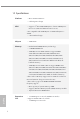
1.2 Specifications Platform CPU Chipset English 2 • Micro ATX Form Factor • Solid Capacitor design • Supports 3rd Gen AMD AM4 Ryzen™ / future AMD Ryzen™ Processors (3000 and 4000 Series Processors)* * Not compatible with AMD Ryzen™ 5 3400G and Ryzen™ 3 3200G.
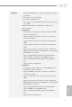
A520M-HDV A520M-HVS • Integrated AMD RadeonTM Vega Series Graphics in Ryzen Series APU* * Actual support may vary by CPU • DirectX 12, Pixel Shader 5.0 • Shared memory default 2GB. Max Shared memory supports up to 16GB. * The Max shared memory 16GB requires 32GB system memory installed. A520M-HDV: • Three graphics output options: D-Sub, DVI-D and HDMI • Supports Triple Monitor • Supports HDMI 2.1 with max. resolution up to 4K x 2K (4096x2160) @ 60Hz • Supports DVI-D with max.
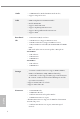
Audio • 7.1 CH HD Audio (Realtek ALC887 Audio Codec) • Supports Surge Protection LAN • • • • • • PCIE x1 Gigabit LAN 10/100/1000 Mb/s Realtek RTL8111H Supports Wake-On-LAN Supports Lightning/ESD Protection Supports Energy Efficient Ethernet 802.3az Supports PXE English Rear Panel I/O 1 x PS/2 Mouse/Keyboard Port 2 x USB 2.0 Ports (Supports ESD Protection) 4 x USB 3.
A520M-HDV A520M-HVS * The Chassis Fan supports the water cooler fan of maximum 1A (12W) fan power. * CHA_FAN2 can auto detect if 3-pin or 4-pin fan is in use. 1 x 24 pin ATX Power Connector 1 x 4 pin 12V Power Connector 1 x Front Panel Audio Connector 2 x USB 2.0 Headers (Support 4 USB 2.0 ports) (Supports ESD Protection) • 1 x USB 3.2 Gen1 Header (Supports 2 USB 3.2 Gen1 ports) (Supports ESD Protection) • • • • AMI UEFI Legal BIOS with GUI support Supports “Plug and Play” ACPI 5.
1.3 Motherboard Layout A520M-HDV: 2 1 3 CPU_FAN1 ATX12V PS2 Keyboard/ Mouse SPI_TPM_J1 BIOS ROM 4 5 1 1 17 M2_1 Center: FRONT Top: LINE IN Bottom: MIC IN CHA_FAN1 USB3_5_6 CMOS Battery RJ-45 LAN USB 3.2 Gen1 T: USB3 B: USB4 ATXPWR1 FSB800 USB 3.2 Gen1 T: USB1 B: USB2 DDR4_A2 (64 bit, 288-pin module) SOCKET AM4 DDR4_A1 (64 bit, 288-pin module) HDMI1 A520M-HDV USB 2.0 T: USB1 B: USB2 PCIE1 Ultra M.
A520M-HDV A520M-HVS A520M-HVS: 2 1 3 CPU_FAN1 ATX12V PS2 Keyboard/ Mouse SPI_TPM_J1 BIOS ROM 5 1 1 17 M2_1 Center: FRONT Top: LINE IN Bottom: MIC IN CHA_FAN1 4 USB3_5_6 CMOS Battery RJ-45 LAN USB 3.2 Gen1 T: USB3 B: USB4 ATXPWR1 FSB800 USB 3.2 Gen1 T: USB1 B: USB2 DDR4_A2 (64 bit, 288-pin module) SOCKET AM4 DDR4_A1 (64 bit, 288-pin module) HDMI1 A520M-HVS USB 2.0 T: USB1 B: USB2 PCIE1 Ultra M.
No. Description English 8 1 ATX 12V Power Connector (ATX12V1) 2 CPU Fan Connector (CPU_FAN1) 3 2 x 288-pin DDR4 DIMM Slots (DDR4_A1, DDR4_B1) 4 ATX Power Connector (ATXPWR1) 5 USB 3.2 Gen1 Header (USB3_5_6) 6 SATA3 Connector (SATA3_3) (Upper), SATA3 Connector (SATA3_4) (Lower) 7 SATA3 Connector (SATA3_4) (Upper), SATA3 Connector (SATA3_2) (Lower) 8 System Panel Header (PANEL1) 9 Chassis Intrusion and Speaker Header (SPK_CI1) 10 Chassis Fan Connector (CHA_FAN2) 11 USB 2.
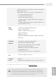
A520M-HDV A520M-HVS 1.4 I/O Panel A520M-HDV: 1 11 2 10 8 9 No. Description 3 4 5 7 6 No. Description 1 USB 2.0 Ports (USB_12) 7 USB 3.2 Gen1 Ports (USB3_34) 2 D-Sub Port 8 USB 3.2 Gen1 Ports (USB3_12) 3 LAN RJ-45 Port* 9 DVI-D Port 4 Line In (Light Blue)** 10 HDMI Port 5 Front Speaker (Lime)** 11 PS/2 Mouse/Keyboard Port 6 Microphone (Pink)** A520M-HVS: 10 2 9 No. Description 8 3 4 5 7 6 No. Description 1 USB 2.
* There are two LEDs on each LAN port. Please refer to the table below for the LAN port LED indications. ACT/LINK LED SPEED LED LAN Port Activity / Link LED Speed LED Status Description Status Description Off Blinking On No Link Data Activity Link Off Orange Green 10Mbps connection 100Mbps connection 1Gbps connection ** Function of the Audio Ports in 7.
A520M-HDV A520M-HVS Chapter 2 Installation This is a Micro ATX form factor motherboard. Before you install the motherboard, study the configuration of your chassis to ensure that the motherboard fits into it. Pre-installation Precautions Take note of the following precautions before you install motherboard components or change any motherboard settings. English • Make sure to unplug the power cord before installing or removing the motherboard.
2.1 Installing the CPU Unplug all power cables before installing the CPU.
A520M-HDV A520M-HVS English 3 13
2.2 Installing the CPU Fan and Heatsink After you install the CPU into this motherboard, it is necessary to install a larger heatsink and cooling fan to dissipate heat. You also need to spray thermal grease between the CPU and the heatsink to improve heat dissipation. Make sure that the CPU and the heatsink are securely fastened and in good contact with each other. Please turn off the power or remove the power cord before changing a CPU or heatsink.
A520M-HDV A520M-HVS 3 CP U_ FA N1 English 4 15
Installing the AM4 Box Cooler SR2 1 2 English 16
A520M-HDV A520M-HVS English 3 17
CP U_ FA N 1 4 *The diagrams shown here are for reference only. The headers might be in a different position on your motherboard.
A520M-HDV A520M-HVS Installing the AM4 Box Cooler SR3 1 English 2 19
3 4 English 20
A520M-HDV A520M-HVS CP U_ FA N1 5 CP U_ FA N 1 6 RG B _L ED 2 *The diagrams shown here are for reference only. The headers might be in a different position on your motherboard.
2.3 Installing Memory Modules (DIMM) This motherboard provides two 288-pin DDR4 (Double Data Rate 4) DIMM slots, and supports Dual Channel Memory Technology. 1. For dual channel configuration, you always need to install identical (the same brand, speed, size and chip-type) DDR4 DIMM pairs. 2. It is unable to activate Dual Channel Memory Technology with only one memory module installed. 3.
A520M-HDV A520M-HVS The DIMM only fits in one correct orientation. It will cause permanent damage to the motherboard and the DIMM if you force the DIMM into the slot at incorrect orientation.
2.4 Expansion Slots (PCI Express Slots) There are 2 PCI Express slots on the motherboard. Before installing an expansion card, please make sure that the power supply is switched off or the power cord is unplugged. Please read the documentation of the expansion card and make necessary hardware settings for the card before you start the installation. PCIe slots: PCIE1 (PCIe 3.0 x1 slot) is used for PCI Express x1 lane width cards. PCIE2 (PCIe 3.
A520M-HDV A520M-HVS 2.5 Jumpers Setup The illustration shows how jumpers are setup. When the jumper cap is placed on the pins, the jumper is “Short”. If no jumper cap is placed on the pins, the jumper is “Open”. Clear CMOS Jumper (CLRMOS1) (see p.6 or 7, No. 14) Short: Clear CMOS 2-pin Jumper Open: Default CLRMOS1 allows you to clear the data in CMOS. To clear and reset the system parameters to default setup, please turn off the computer and unplug the power cord from the power supply.
2.6 Onboard Headers and Connectors Onboard headers and connectors are NOT jumpers. Do NOT place jumper caps over these headers and connectors. Placing jumper caps over the headers and connectors will cause permanent damage to the motherboard. System Panel Header (9-pin PANEL1) (see p.6 or 7, No. 8) PLED+ PLEDPWRBTN# GND 1 GND RESET# GND HDLEDHDLED+ Connect the power switch, reset switch and system status indicator on the chassis to this header according to the pin assignments below.
A520M-HDV A520M-HVS Chassis Intrusion and Speaker Header (7-pin SPK_CI1) (see p.6 or 7, No. 9) Please connect the chassis intrusion and the chassis speaker to this header. SPEAKER DUMMY DUMMY +5V 1 USB 2.0 Headers (9-pin USB_3_4) (see p.6 or 7, No. 11) (9-pin USB_5_6) (see p.6 or 7, No. 12) USB 3.2 Gen1 Header (19-pin USB3_5_6) (see p.6 or 7, No. 5) SATA3_1 SATA3_3 Serial ATA3 Connectors Vertical: (SATA3_1: see p.6 or 7, No. 7) (Upper) (SATA3_2: see p.6 or 7, No. 7) (Lower) (SATA3_3: see p.
1. High Definition Audio supports Jack Sensing, but the panel wire on the chassis must support HDA to function correctly. Please follow the instructions in our manual and chassis manual to install your system. 2. If you use an AC’97 audio panel, please install it to the front panel audio header by the steps below: A. Connect Mic_IN (MIC) to MIC2_L. B. Connect Audio_R (RIN) to OUT2_R and Audio_L (LIN) to OUT2_L. C. Connect Ground (GND) to Ground (GND). D. MIC_RET and OUT_RET are for the HD audio panel only.
A520M-HDV A520M-HVS ATX 12V Power Connector (4-pin ATX12V1) (see p.6 or 7, No. 1) Please connect an ATX 12V power supply to this connector. *The power supply plug fits into this connector in only one orientation. Serial Port Header (9-pin COM1) (see p.6 or 7, No. 13) RRXD1 DDTR#1 DDSR#1 CCTS#1 1 This COM1 header supports a serial port module. RRI#1 RRTS#1 GND TTXD1 DDCD#1 +3.
2.7 M.2_SSD (NGFF) Module Installation Guide The M.2, also known as the Next Generation Form Factor (NGFF), is a small size and versatile card edge connector that aims to replace mPCIe and mSATA. The Ultra M.2 Socket supports M Key type 2242/2260/2280 M.2 SATA3 6.0 Gb/s module and M.2 PCI Express module up to Gen3 x4 (32 Gb/s). Installing the M.2_SSD (NGFF) Module Step 1 Prepare a M.2_SSD (NGFF) module and the screw. Step 2 3 2 Depending on the PCB type and length of your M.
A520M-HDV A520M-HVS Step 3 C B Move the standoff based on the module type and length. The standoff is placed at the nut location C by default. Skip Step 3 and 4 and go straight to Step 5 if you are going to use the default nut. Otherwise, release the standoff by hand. A Step 4 C B Peel off the yellow protective film on the nut to be used. Hand tighten the standoff into the desired nut location on the motherboard. A Step 5 Gently insert the M.2 (NGFF) SSD module into the M.2 slot.
Step 6 C English 32 NUT2 NUT1 Tighten the screw with a screwdriver to secure the module into place. Please do not overtighten the screw as this might damage the module.
A520M-HDV A520M-HVS M.
Chapter 3 Software and Utilities Operation 3.1 Installing Drivers The Support CD that comes with the motherboard contains necessary drivers and useful utilities that enhance the motherboard’s features. Running The Support CD To begin using the support CD, insert the CD into your CD-ROM drive. The CD automatically displays the Main Menu if “AUTORUN” is enabled in your computer. If the Main Menu does not appear automatically, locate and double click on the file “ASRSETUP.
A520M-HDV A520M-HVS 3.2 ASRock Motherboard Utility (A-Tuning) ASRock Motherboard Utility (A-Tuning) is ASRock’s multi purpose software suite with a new interface, more new features and improved utilities. 3.2.1 Installing ASRock Motherboard Utility (A-Tuning) ASRock Motherboard Utility (A-Tuning) can be downloaded from ASRock Live Update & APP Shop. After the installation, you will find the icon “ASRock Motherboard Utility (A-Tuning)“ on your desktop.
OC Tweaker Configurations for overclocking the system. System Info View information about the system. *The System Browser tab may not appear for certain models.
A520M-HDV A520M-HVS FAN-Tastic Tuning Configure up to five different fan speeds using the graph. The fans will automatically shift to the next speed level when the assigned temperature is met. Settings English Configure ASRock ASRock Motherboard Utility (A-Tuning). Click to select "Auto run at Windows Startup" if you want ASRock Motherboard Utility (A-Tuning) to be launched when you start up the Windows operating system.
3.3 ASRock Live Update & APP Shop The ASRock Live Update & APP Shop is an online store for purchasing and downloading software applications for your ASRock computer. You can quickly and easily install various apps and support utilities. With ASRock Live Update & APP Shop, you can optimize your system and keep your motherboard up to date simply with a few clicks. Double-click utility.
A520M-HDV A520M-HVS 3.3.2 Apps When the "Apps" tab is selected, you will see all the available apps on screen for you to download. Installing an App Step 1 Find the app you want to install. The most recommended app appears on the left side of the screen. The other various apps are shown on the right. Please scroll up and down to see more apps listed. You can check the price of the app and whether you have already intalled it or not.
Step 3 If you want to install the app, click on the red icon to start downloading. Step 4 When installation completes, you can find the green "Installed" icon appears on the upper right corner. English To uninstall it, simply click on the trash can icon *The trash icon may not appear for certain apps. 40 .
A520M-HDV A520M-HVS Upgrading an App You can only upgrade the apps you have already installed. When there is an available new version for your app, you will find the mark of "New Version" appears below the installed app icon. Step 1 Click on the app icon to see more details. Step 2 to start upgrading.
3.3.3 BIOS & Drivers Installing BIOS or Drivers When the "BIOS & Drivers" tab is selected, you will see a list of recommended or critical updates for the BIOS or drivers. Please update them all soon. Step 1 Please check the item information before update. Click on Step 2 Click to select one or more items you want to update. Step 3 Click Update to start the update process. English 42 to see more details.
A520M-HDV A520M-HVS 3.3.4 Setting In the "Setting" page, you can change the language, select the server location, and English determine if you want to automatically run the ASRock Live Update & APP Shop on Windows startup.
Chapter 4 UEFI SETUP UTILITY 4.1 Introduction This section explains how to use the UEFI SETUP UTILITY to configure your system. You may run the UEFI SETUP UTILITY by pressing or right after you power on the computer, otherwise, the Power-On-Self-Test (POST) will continue with its test routines. If you wish to enter the UEFI SETUP UTILITY after POST, restart the system by pressing + + , or by pressing the reset button on the system chassis.
A520M-HDV A520M-HVS 4.1.2 Navigation Keys Use < > key or < > key to choose among the selections on the menu bar, and use < > key or < > key to move the cursor up or down to select items, then press to get into the sub screen. You can also use the mouse to click your required item. Please check the following table for the descriptions of each navigation key.
4.2 Main Screen When you enter the UEFI SETUP UTILITY, the Main screen will appear and display the system overview.
A520M-HDV A520M-HVS 4.3 OC Tweaker Screen In the OC Tweaker screen, you can set up overclocking features. Because the UEFI software is constantly being updated, the following UEFI setup screens and descriptions are for reference purpose only, and they may not exactly match what you see on your screen. SoC/Uncore OC Voltage(VID) Specify the SoC/Uncore voltage (VDD_SOC) in mV to support memory and Infinity Fabric overclocking. VDD_SOC also determines the GPU voltage on processors with integrated graphics.
CLD0 VDDG IOD Voltage Control AMD Overclocking Setup VDDG IOD represents voltage for the data portion of the Infinity Fabric. It is derived from the CPU SoC/Uncore Voltage (VDD_SOC). VDDG can approach but not exceed VDD_SOC. DRAM Information Load XMP Setting Load XMP settings to overclock the memory and perform beyond standard specifications. DRAM Frequency If [Auto] is selected, the motherboard will detect the memory module(s) inserted and assign the appropriate frequency automatically.
A520M-HDV A520M-HVS Load User Default Load previously saved user defaults. Save User UEFI Setup Profile to Disk It helps you to save current UEFI settings as an user profile to disk. Load User UEFI Setup Profile from Disk English You can load previous saved profile from the disk.
4.4 Advanced Screen In this section, you may set the configurations for the following items: CPU Configuration, Onboard Devices Configuration, Storage Configuration, ACPI Configuration, Super IO Configuration, Trusted Computing, AMD PBS, AMD Overclocking and AMD CBS. Setting wrong values in this section may cause the system to malfunction. UEFI Configuration Active Page on Entry Select the default page when entering the UEFI setup utility.
A520M-HDV A520M-HVS 4.4.1 CPU Configuration PSS Support Use this to enable or disable the generation of ACPI_PPC, _PSS, and _PCT objects. NX Mode Use this to enable or disable NX mode. SVM Mode When this is set to [Enabled], a VMM (Virtual Machine Architecture)can utilize the additional hardware capabilities provided by AMD-V. The default value is [Enabled]. Coniguration options: [Enabled] and [Disabled]. SMT Mode This item can be used to disable symmetric multithreading.
4.4.2 Onboard Devices Configuration SR-IOV Support Enable/disable the SR-IOV (Single Root IO Virtualization Support) if the system has SR-IOV capable PCIe devices. UMA Frame buffer Size (Only for processor with integrated graphics) This item allows you to set the size of the UMA frame buffer. Gnb HD Audio Enable/disable onboard HD audio. Set to Auto to enable onboard HD audio and automatically disable it when a sound card is installed. Front Panel Enable/disable front panel HD audio.
A520M-HDV A520M-HVS PS2 Y-Cable English Enable the PS2 Y-Cable or set this option to Auto.
4.4.3 Storage Configuration SATA Mode AHCI: Supports new features that improve performance. RAID: Combine multiple disk drives into a logical unit. SATA Hot Plug Enable/disable the SATA Hot Plug function.
A520M-HDV A520M-HVS 4.4.4 ACPI Configuration Suspend to RAM It is recommended to select auto for ACPI S3 power saving. Deep Sleep Configure deep sleep mode for power saving when the computer is shut down. PS/2 Keyboard S4/S5 Wakeup Support Allow the system to be waked up by a PS/2 Keyboard in S4/S5. PCIE Devices Power On Allow the system to be waked up by a PCIE device and enable wake on LAN. RTC Alarm Power On English Allow the system to be waked up by the real time clock alarm.
4.4.5 Super IO Configuration Serial Port 1 Enable or disable the Serial port 1. Serial Port Address Select the address of the Serial port.
A520M-HDV A520M-HVS 4.4.6 Trusted Computing Security Device Support English Enable or disable BIOS support for security device.
4.4.7 AMD PBS The AMD PBS menu accesses AMD specific features.
A520M-HDV A520M-HVS 4.4.8 AMD Overclocking English The AMD Overclocking menu accesses options for configuring CPU frequency and voltage.
4.4.9 AMD CBS The AMD CBS menu accesses AMD specific features.
A520M-HDV A520M-HVS 4.5 Tools Easy RAID Installer Easy RAID Installer helps you to copy the RAID driver from the support CD to your USB storage device. After copying the drivers please change the SATA mode to RAID, then you can start installing the operating system in RAID mode. SSD Secure Erase Tool Use this tool to securely erase SSD. NVME Sanitization Tool After you sanitize SSD, all user data will be permantly destroyed on the SSD and cannot be recovered.
4.6 Hardware Health Event Monitoring Screen This section allows you to monitor the status of the hardware on your system, including the parameters of the CPU temperature, motherboard temperature, fan speed and voltage. CPU FAN1 Setting Select a fan mode for CPU Fan 1, or choose Customize to set 5 CPU temperatures and assign a respective fan speed for each temperature. CPU FAN1 Temp Source Select a fan temperature source for CPU Fan 1.
A520M-HDV A520M-HVS Fan-Tastic Select a fan mode for Fan, or choose Customize to set 5 CPU temperatures and assign a respective fan speed for each temperature. FanTuning English Detect the lowest fan speed in the system. Iy may take 3-5 minutes to complete.
4.7 Security Screen In this section you may set or change the supervisor/user password for the system. You may also clear the user password. Supervisor Password Set or change the password for the administrator account. Only the administrator has authority to change the settings in the UEFI Setup Utility. Leave it blank and press enter to remove the password. User Password Set or change the password for the user account. Users are unable to change the settings in the UEFI Setup Utility.
A520M-HDV A520M-HVS 4.8 Boot Screen This section displays the available devices on your system for you to configure the boot settings and the boot priority. Boot From Onboard LAN Allow the system to be waked up by the onboard LAN. Setup Prompt Timeout Configure the number of seconds to wait for the setup hot key. Fast Boot English Fast Boot minimizes your computer's boot time. In fast mode you may not boot from an USB storage device.
CSM (Compatibility Support Module) CSM Enable to launch the Compatibility Support Module. Please do not disable unless you’re running a WHCK test. Launch PXE OpROM Policy Select UEFI only to run those that support UEFI option ROM only. Select Legacy only to run those that support legacy option ROM only. Select Do not launch to not execute both legacy and UEFI option ROM. Launch Storage OpROM Policy Select UEFI only to run those that support UEFI option ROM only.
A520M-HDV A520M-HVS AddOn ROM Display English Enable AddOn ROM Display to see the AddOn ROM messages or configure the AddOn ROM if you’ve enabled Full Screen Logo. Disable for faster boot speed.
4.9 Exit Screen Save Changes and Exit When you select this option the following message, “Save configuration changes and exit setup?” will pop out. Select [OK] to save changes and exit the UEFI SETUP UTILITY. Discard Changes and Exit When you select this option the following message, “Discard changes and exit setup?” will pop out. Select [OK] to exit the UEFI SETUP UTILITY without saving any changes. Discard Changes When you select this option the following message, “Discard changes?” will pop out.
Contact Information If you need to contact ASRock or want to know more about ASRock, you’re welcome to visit ASRock’s website at http://www.asrock.com; or you may contact your dealer for further information. For technical questions, please submit a support request form at https://event.asrock.com/tsd.asp ASRock Incorporation 2F., No.37, Sec. 2, Jhongyang S. Rd., Beitou District, Taipei City 112, Taiwan (R.O.C.) ASRock EUROPE B.V.
DECLARATION OF CONFORMITY Per FCC Part 2 Section 2.1077(a) Responsible Party Name: Address: Phone/Fax No: ASRock Incorporation 13848 Magnolia Ave, Chino, CA91710 +1-909-590-8308/+1-909-590-1026 hereby declares that the product Product Name : Motherboard Model Number : A520M-HDV / A520M-HVS Conforms to the following specifications: FCC Part 15, Subpart B, Unintentional Radiators Supplementary Information: This device complies with part 15 of the FCC Rules.
EU Declaration of Conformity For the following equipment: Motherboard (Product Name) A520M-HDV / A520M-HVS / ASRock (Model Designation / Trade Name) ASRock Incorporation (Manufacturer Name) 2F., No.37, Sec. 2, Jhongyang S. Rd., Beitou District, Taipei City 112, Taiwan (R.O.C.