A75 Pro4 User Manual Version 1.1 Published June 2011 Copyright©2011 ASRock INC. All rights reserved.
Copyright Notice: No part of this manual may be reproduced, transcribed, transmitted, or translated in any language, in any form or by any means, except duplication of documentation by the purchaser for backup purpose, without written consent of ASRock Inc. Products and corporate names appearing in this manual may or may not be registered trademarks or copyrights of their respective companies, and are used only for identification or explanation and to the owners’ benefit, without intent to infringe.
Contents 1. Introduction................................................................. 5 1.1 1.2 1.3 1.4 Package Contents ..................................................................... Specifications............................................................................. Motherboard Layout ................................................................. I/O Panel .................................................................................. 5 6 12 13 2. Installation ..................
3. UEFI SETUP UTILITY.......................................................... 48 3.1 3.2 3.3 3.4 3.5 3.6 3.7 3.8 Introduction ................................................................................ 3.1.1 UEFI Menu Bar ................................................................ 3.1.2 Navigation Keys ............................................................... Main Screen ............................................................................... OC Tweaker Screen....................
1. Introduction Thank you for purchasing ASRock A75 Pro4 motherboard, a reliable motherboard produced under ASRock’s consistently stringent quality control. It delivers excellent performance with robust design conforming to ASRock’s commitment to quality and endurance. In this manual, chapter 1 and 2 contain introduction of the motherboard and stepby-step guide to the hardware installation. Chapter 3 and 4 contain the configuration guide to BIOS setup and information of the Support CD.
1.2 Specifications Platform CPU Chipset Memory Expansion Slot Graphics - ATX Form Factor: 12.0-in x 8.8-in, 30.5 cm x 22.4 cm - All Solid Capacitor design - Support for Socket FM1 100W processors - V4 + 1 Power Phase Design - Supports AMD’s Cool ‘n’ QuietTM Technology - UMI-Link GEN2 - AMD A75 FCH (Hudson-D3) - Dual Channel DDR3 Memory Technology (see CAUTION 1) - 4 x DDR3 DIMM slots - Support DDR3 2400+(OC)/1866(OC)/1600(OC)/1333/1066/ 800 non-ECC, un-buffered memory (see CAUTION 2) - Max.
Audio - 7.1 CH HD Audio with Content Protection (Realtek ALC892 Audio Codec) - Premium Blu-ray audio support - Supports THX TruStudioTM LAN - PCIE x1 Gigabit LAN 10/100/1000 Mb/s - Realtek RTL8111E - Supports Wake-On-LAN - Supports LAN Cable Detection - Supports Energy Efficient Ethernet 802.3az - Supports PXE I/O Panel - 1 x PS/2 Mouse/Keyboard Port - 1 x D-Sub Port - 1 x DVI-D Port - 1 x HDMI Port - 1 x Optical SPDIF Out Port - 2 x Ready-to-Use USB 2.
Smart Switch BIOS Feature Support CD Unique Feature Hardware Monitor OS Certifications - 1 x Clear CMOS Switch with LED - 1 x Power Switch with LED - 1 x Reset Switch with LED - 32Mb AMI UEFI Legal BIOS with GUI support - Supports “Plug and Play” - ACPI 1.1 Compliance Wake Up Events - Supports jumperfree - SMBIOS 2.3.1 Support - DRAM, VDDP, VDDR, SB Voltage Multi-adjustment - Drivers, Utilities, AntiVirus Software (Trial Version), AMD Live! Explorer, AMD Fusion, CyberLink MediaEspresso 6.
CAUTION! 1. 2. 3. 4. 5. 6. This motherboard supports Dual Channel Memory Technology. Before you implement Dual Channel Memory Technology, make sure to read the installation guide of memory modules on page 17 for proper installation. Whether 2400/1866/1600MHz memory speed is supported depends on the CPU you adopt. If you want to adopt DDR3 2400/1866/1600 memory module on this motherboard, please refer to the memory support list on our website for the compatible memory modules.
9. ASRock Instant Flash is a BIOS flash utility embedded in Flash ROM. This convenient BIOS update tool allows you to update system BIOS without entering operating systems first like MS-DOS or Windows®. With this utility, you can press key during the POST or press key to BIOS setup menu to access ASRock Instant Flash.
15. EuP, stands for Energy Using Product, was a provision regulated by European Union to define the power consumption for the completed system. According to EuP, the total AC power of the completed system shall be under 1.00W in off mode condition. To meet EuP standard, an EuP ready motherboard and an EuP ready power supply are required. According to Intel’s suggestion, the EuP ready power supply must meet the standard of 5v standby power efficiency is higher than 50% under 100 mA current consumption.
1.3 Motherboard Layout 1 2 3 6 5 4 8 7 22.4cm (8.8-in) HDMI 1.4a Bottom: Optical SPDIF Center: REAR SPK Top: CTR BASS LAN CHA_FAN3 Center: FRONT Top: LINE IN Bottom: MIC IN 41 40 A75 Pro4 Dual Graphics PCIE2 AUDIO CODEC 10 DX11 CMOS BATTERY AMD A75 FCH (Hudson-D3) Chipset USB 3.0 PCI1 1 X Fast USB CLRCMOS1 PCIE4 32Mb BIOS 35 PCI2 1394a Dr.
1.4 I/O Panel 1 17 1 2 *3 ** 4 5 6 7 8 *** 9 3 2 16 15 4 PS/2 Mouse/Keyboard Port (Green/Purple) 10 D-Sub Port 11 USB 2.0 Ports (USB23) 12 LAN RJ-45 Port **** 13 Central / Bass (Orange) 14 Rear Speaker (Black) 15 Optical SPDIF Out Port 16 Line In (Light Blue) 17 Front Speaker (Lime) 8 6 9 7 10 11 13 12 14 5 Microphone (Pink) USB 3.0 Ports (USB01) IEEE 1394 Port (IEEE 1394) eSATA3 Connector Clear CMOS Switch (CLRCBTN) HDMI Port DVI-D Port USB 3.
To enable Multi-Streaming function, you need to connect a front panel audio cable to the front panel audio header. After restarting your computer, you will find “Mixer” tool on your system. Please select “Mixer ToolBox” , click “Enable playback multi-streaming”, and click “ok”. Choose “2CH”, “4CH”, “6CH”, or “8CH” and then you are allowed to select “Realtek HDA Primary output” to use Rear Speaker, Central/Bass, and Front Speaker, or select “Realtek HDA Audio 2nd output” to use front panel audio.
2. Installation This is an ATX form factor (12.0-in x 8.8-in, 30.5 cm x 22.4 cm) motherboard. Before you install the motherboard, study the configuration of your chassis to ensure that the motherboard fits into it. Pre-installation Precautions Take note of the following precautions before you install motherboard components or change any motherboard settings. Before you install or remove any component, ensure that the power is switched off or the power cord is detached from the power supply.
2.1 CPU Installation Step 1. Step 2. Step 3. o Unlock the socket by lifting the lever up to a 90 angle. Position the CPU directly above the socket such that the CPU corner with the golden triangle matches the socket corner with a small triangle. Carefully insert the CPU into the socket until it fits in place. The CPU fits only in one correct orientation. DO NOT force the CPU into the socket to avoid bending of the pins. Step 4.
2.3 Installation of Memory Modules (DIMM) This motherboard provides four 240-pin DDR3 (Double Data Rate 3) DIMM slots, and supports Dual Channel Memory Technology. For dual channel configuration, you always need to install identical (the same brand, speed, size and chip-type) DDR3 DIMM pair in the slots of the same color. In other words, you have to install identical DDR3 DIMM pair in Dual Channel A (DDR3_ A1 and DDR3_B1; Blue slots; see p.12 No.
Installing a DIMM Please make sure to disconnect power supply before adding or removing DIMMs or the system components. Step 1. Step 2. Unlock a DIMM slot by pressing the retaining clips outward. Align a DIMM on the slot such that the notch on the DIMM matches the break on the slot. notch break notch break The DIMM only fits in one correct orientation. It will cause permanent damage to the motherboard and the DIMM if you force the DIMM into the slot at incorrect orientation. Step 3.
2.4 Expansion Slots (PCI and PCI Express Slots) There are 3 PCI slots and 4 PCI Express slots on this motherboard. PCI Slots: PCI slots are used to install expansion cards that have the 32-bit PCI interface. PCIE Slots: PCIE1 / PCIE3 (PCIE x1 slot; White) is used for PCI Express cards with x1 lane width cards, such as Gigabit LAN card and SATA2 card.
2.5 CrossFireXTM and Quad CrossFireXTM Operation Guide This motherboard supports CrossFireX TM and Quad CrossFireX TM feature. CrossFireX TM technology offers the most advantageous means available of combining multiple high performance Graphics Processing Units (GPU) in a single PC. Combining a range of different operating modes with intelligent software design and an innovative interconnect mechanism, CrossFireX TM enables the highest possible level of performance and image quality in any 3D application.
Step 2. Connect two Radeon graphics cards by installing CrossFire Bridge on CrossFire Bridge Interconnects on the top of Radeon graphics cards. (CrossFire Bridge is provided with the graphics card you purchase, not bundled with this motherboard. Please refer to your graphics card vendor for details.) CrossFire Bridge or Step 3. Connect the DVI monitor cable to the DVI connector on the Radeon graphics card on PCIE2 slot.
2.5.2 Driver Installation and Setup Step 1. Step 2. Power on your computer and boot into OS. Remove the AMD driver if you have any VGA driver installed in your system. The Catalyst Uninstaller is an optional download. We recommend using this utility to uninstall any previously installed Catalyst drivers prior to installation. Please check AMD website for AMD driver updates. Step 3. Step 4. Step 5. Install the required drivers to your system. For Windows® XP OS: A.
Although you have selected the option “Enable CrossFireTM”, the CrossFireXTM function may not work actually. Your computer will automatically reboot. After restarting your computer, please confirm whether the option “Enable CrossFireTM” in “ATI Catalyst Control Center” is selected or not; if not, please select it again, and then you are able to enjoy the benefit of CrossFireXTM feature. Step 7. You can freely enjoy the benefit of CrossFireXTM or Quad CrossFireXTM feature.
2.6 AMD Dual Graphics Operation Guide This motherboard supports AMD Dual Graphics feature. AMD Dual Graphics brings multi-GPU performance capabilities by enabling an AMD A75 FCH (Hudson-D3) integrated graphics processor and a discrete graphics processor to operate simultaneously with combined output to a single display for blisteringly-fast frame rates. Currently, AMD Dual Graphics Technology is only supported with Windows® 7 OS, and is not available with Windows® VistaTM / XP OS.
Step 7. You can also click “AMD VISION Engine Control Center” on your Windows® taskbar to enter AMD VISION Engine Control Center. AMD VISION Engine Control Center Step 8. In AMD VISION Engine Control Center, please choose “Performance”. Click “AMD CrossFireTM”. Step 9. Click “Enable CrossFireTM” and click “Apply“ to save your change. Step 10. Reboot your system. Then you can freely enjoy the benefit of Dual Graphics feature.
2.7 Dual Monitor and Surround Display Features Dual Monitor Feature This motherboard supports dual monitor feature. With the internal VGA output support (DVI-D, D-Sub and HDMI), you can easily enjoy the benefits of dual monitor feature without installing any add-on VGA card to this motherboard. This motherboard also provides independent display controllers for DVI-D, D-Sub and HDMI to support dual VGA output so that DVI-D, D-sub and HDMI can drive same or different display contents.
Surround Display Feature This motherboard supports surround display upgrade. With the internal VGA output support (DVI-D, D-Sub and HDMI) and external add-on PCI Express VGA cards, you can easily enjoy the benefits of surround display feature. Please refer to the following steps to set up a surround display environment: 1. Install the PCI Express VGA cards on PCIE2 and PCIE4 slots. Please refer to page 19 for proper expansion card installation procedures for details. 2.
For Windows® 7 / 7 64-bit / VistaTM / VistaTM 64-bit OS: Right click the desktop, choose “Personalize”, and select the “Display Settings” tab so that you can adjust the parameters of the multi-monitor according to the steps below. A. Click the number ”2” icon. B. Click the items “This is my main monitor” and “Extend the desktop onto this monitor”. C. Click “OK” to save your change. D. Repeat steps A through C for the display icon identified by the number three to six. 6. Use Surround Display.
2.8 ASRock Smart Remote Installation Guide ASRock Smart Remote is only used for ASRock motherboard with CIR header. Please refer to below procedures for the quick installation and usage of ASRock Smart Remote. Step1. Find the CIR header located next to the USB 2.0 header on ASRock motherboard. USB 2.0 header (9-pin, blue) CIR header (4-pin, white) Step2. Connect the front USB cable to the USB 2.0 header (as below, pin 1-5) and the CIR header.
2.9 Jumpers Setup The illustration shows how jumpers are setup. When the jumper cap is placed on pins, the jumper is “Short”. If no jumper cap is placed on pins, the jumper is “Open”. The illustration shows a 3-pin jumper whose pin1 and pin2 are “Short” when jumper cap is placed on these 2 pins. Jumper Clear CMOS Jumper Setting Description (CLRCMOS1) (see p.12, No. 10) Default Clear CMOS Note: CLRCMOS1 allows you to clear the data in CMOS.
2.10 Onboard Headers and Connectors Onboard headers and connectors are NOT jumpers. Do NOT place jumper caps over these headers and connectors. Placing jumper caps over the headers and connectors will cause permanent damage of the motherboard! Serial ATA3 Connectors These five Serial ATA3 (SATA3) connectors support SATA3_5 (SATA3_5: see p.12, No. 12) SATA3_3 (SATA3_4: see p.12, No. 13) SATA3_1 (SATA3_3: see p.12, No. 14) SATA3_4 (SATA3_2: see p.12, No. 16) SATA3_2 (SATA3_1: see p.12, No.
IRTX +5VSB Infrared Module Header This header supports an DUMMY (5-pin IR1) (see p.12 No. 23) 1 optional wireless transmitting and receiving infrared module. GND IRRX Consumer Infrared Module Header 1 GND IRTX IRRX ATX+5VSB (4-pin CIR1) (see p.12 No. 29) GND PRESENCE# MIC_RET OUT_RET Front Panel Audio Header (9-pin HD_AUDIO1) (see p.12 No. 33) 1 OUT2_L J_SENSE OUT2_R MIC2_R MIC2_L This header can be used to connect the remote controller receiver.
RESET (Reset Switch): Connect to the reset switch on the chassis front panel. Press the reset switch to restart the computer if the computer freezes and fails to perform a normal restart. PLED (System Power LED): Connect to the power status indicator on the chassis front panel. The LED is on when the system is operating. The LED keeps blinking when the sys-tem is in S1 sleep state. The LED is off when the system is in S3/S4 sleep state or powered off (S5).
CPU Fan Connectors (4-pin CPU_FAN1) (see p.12 No. 5) FAN_SPEED_CONTROL CPU_FAN_SPEED +12V GND 1 2 3 4 Please connect the CPU fan cable to the connector and match the black wire to the ground pin. Though this motherboard provides 4-Pin CPU fan (Quiet Fan) support, the 3-Pin CPU fan still can work successfully even without the fan speed control function. If you plan to connect the 3-Pin CPU fan to the CPU fan connector on this motherboard, please connect it to Pin 1-3.
Serial port Header This COM1 header supports a serial port module. (9-pin COM1) (see p.12 No.30) HDMI_SPDIF Header (2-pin HDMI_SPDIF1) HDMI_SPDIF header, providing SPDIF audio output to HDMI VGA card, allows the system to connect HDMI Digital TV/ projector/LCD devices. Please connect the HDMI_SPDIF connector of HDMI VGA card to this header. 1 GND (see p.12 No.
2.11 Smart Switches This motherboard has three smart switches: power switch, reset switch and clear CMOS switch, allowing users to quickly turn on/off or reset the system or clear the CMOS values. Power Switch Power Switch is a smart switch, allowing users to quickly turn on/off the system. (PWRBTN) (see p.12 No. 18) Reset Switch (RSTBTN) RESET Reset Switch is a smart switch, allowing users to quickly reset the system.
2.12 Dr. Debug Dr. Debug is used to provide code information, which makes troubleshooting even easier. Please see the diagrams below for reading the Dr. Debug codes. Status Code 0x00 0x01 0x02 0x03 0x04 0x05 0x06 0x07 0x08 0x09 0x0A 0x0B 0x0C – 0x0D 0x0E 0x0F 0x10 0x11 0x12 0x13 0x14 0x15 0x16 0x17 0x18 0x19 0x1A 0x1B 0x1C 0x1D – 0x2A 0x2B 0x2C 0x2D 0x2E 0x2F 0x30 0x31 0x32 0x33 0x34 0x35 0x36 Description Not used Power on.
0x37 0x38 0x39 0x3A 0x3B 0x3C 0x3D 0x3E 0x3F-0x4E 0x4F 0x50 0x51 0x52 0x53 0x54 0x55 0x56 0x57 0x58 0x59 0x5A 0x5B 0x5C-0x5F 0xE0 0xE1 0xE2 0xE3 0xE4-0xE7 0xE8 0xE9 0xEA 0xEB 0xEC-0xEF 0xF0 0xF1 0xF2 0xF3 0xF4 0xF5-0xF7 0xF8 0xF9 0xFA 0xFB – 0xFF 0x60 0X61 Post-Memory North Bridge initialization is started Post-Memory North Bridge initialization (North Bridge module specific) Post-Memory North Bridge initialization (North Bridge module specific) Post-Memory North Bridge initialization (North Bridge module
0x62 0x63 0x64 0x65 0x66 0x67 0x68 0x69 0x6A 0x6B 0x6C 0x6D 0x6E 0x6F 0x70 0x71 0x72 0x73 0x74 0x75 0x76 0x77 0x78 0x79 0x7A – 0x7F 0x80 – 0x8F 0x90 0x91 0x92 0x93 0x94 0x95 0x96 0x97 0x98 0x99 0x9A 0x9B 0x9C 0x9D 0x9E – 0x9F 0xA0 0xA1 0xA2 0xA3 0xA4 0xA5 Installation of the South Bridge Runtime Services CPU DXE initialization is started CPU DXE initialization (CPU module specific) CPU DXE initialization (CPU module specific) CPU DXE initialization (CPU module specific) CPU DXE initialization (CPU module s
0xA6 0xA7 0xA8 0xA9 0xAA 0xAB 0xAC 0xAD 0xAE 0xAF 0xB0 0xB1 0xB2 0xB3 0xB4 0xB5 0xB6 0xB7 0xB8 – 0xBF 0xC0 – 0xCF 0xD0 0xD1 0xD2 0xD3 0xD4 0xD5 0xD6 0xD7 0xD8 0xD9 0xDA 0xDB 0xDC SCSI Detect SCSI Enable Setup Verifying Password Start of Setup Reserved for ASL (see ASL Status Codes section below) Setup Input Wait Reserved for ASL (see ASL Status Codes section below) Ready To Boot event Legacy Boot event Exit Boot Services event Runtime Set Virtual Address MAP Begin Runtime Set Virtual Address MAP End Legacy
2.13 Serial ATA3 (SATA3) Hard Disks Installation This motherboard adopts AMD A75 FCH (Hudson-D3) chipset that supports Serial ATA3 (SATA3) hard disks and RAID (RAID 0, RAID 1 and RAID 10) functions. You may install SATA3 hard disks on this motherboard for internal storage devices. This section will guide you to install the SATA3 hard disks. STEP 1: Install the SATA3 hard disks into the drive bays of your chassis. STEP 2: Connect the SATA power cable to the SATA3 hard disk.
2.15 SATA3 HDD Hot Plug Feature and Operation Guide This motherboard supports Hot Plug feature for SATA3 HDD in RAID / AHCI mode. Please read below operation guide of Hot Plug feature carefully. Before you process the SATA3 HDD Hot Plug, please check below cable accessories from the motherboard gift box pack. A. 7-pin SATA data cable B. SATA power cable with SATA 15-pin power connector interface A. SATA data cable (Red) SATA 7-pin connector B.
How to Hot Plug a SATA3 HDD: Points of attention, before you process the Hot Plug: Please do follow below instruction sequence to process the Hot Plug, improper procedure will cause the SATA3 HDD damage and data loss. Step 1 Please connect SATA power cable 1x4-pin Step 2 Connect SATA data cable to end (White) to the power supply 1x4-pin the motherboard’s SATAII / SATA3 cable. connector.
2.16 Driver Installation Guide To install the drivers to your system, please insert the support CD to your optical drive first. Then, the drivers compatible to your system can be auto-detected and listed on the support CD driver page. Please follow the order from up to bottom side to install those required drivers. Therefore, the drivers you install can work properly. 2.
STEP 3: Use “RAID Installation Guide” to set RAID configuration. Before you start to configure RAID function, you need to check the RAID installation guide in the Support CD for proper configuration. Please refer to the BIOS RAID installation guide part of the document in the following path in the Support CD: .. \ RAID Installation Guide STEP 4: Install Windows® XP / XP 64-bit OS on your system. After step 1, 2, 3, you can start to install Windows® XP / XP 64-bit OS on your system.
2.18 Installing Windows® 7 / 7 64-bit / VistaTM / VistaTM 64-bit / XP / XP 64-bit Without RAID Functions If you want to install Windows® 7 / 7 64-bit / VistaTM / VistaTM 64-bit / XP / XP 64-bit OS on your SATA3 HDDs without RAID functions, please follow below procedures according to the OS you install. 2.18.1 Installing Windows® XP / XP 64-bit Without RAID Functions If you want to install Windows® XP / XP 64-bit on your SATA3 HDDs without RAID functions, please follow below steps.
2.18.2 Installing Windows® 7 / 7 64-bit / VistaTM / VistaTM 64-bit Without RAID Functions If you want to install Windows® 7 / 7 64-bit / VistaTM / VistaTM 64-bit on your SATA3 HDDs without RAID functions, please follow below steps. Using SATA3 HDDs with NCQ and Hot Plug functions (AHCI mode) STEP 1: Set up UEFI. A. Enter UEFI SETUP UTILITY Advanced screen Storage Configuration. B. Set the “SATA Mode” option to [AHCI]. STEP 2: Install Windows® 7 / 7 64-bit / VistaTM / VistaTM 64-bit OS on your system.
3. UEFI SETUP UTILITY 3.1 Introduction This section explains how to use the UEFI SETUP UTILITY to configure your system. The SPI Memory on the motherboard stores the UEFI SETUP UTILITY. You may run the UEFI SETUP UTILITY when you start up the computer. Please press or during the Power-On-Self-Test (POST) to enter the UEFI SETUP UTILITY, otherwise, POST will continue with its test routines.
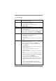
3.1.2 Navigation Keys Please check the following table for the function description of each navigation key.
3.3 OC Tweaker Screen In the OC Tweaker screen, you can set up overclocking features. CPU Configuration Overclock Mode Use this to select Overclock Mode. Configuration options: [Auto] and [Manual]. The default value is [Auto]. APU/PCIE Frequency (MHz) This item appears only when you set the item “Overclock Mode“ to [Manual]. The default value is [100]. Please be noted that overclocking may reduce the D-Sub resolution and cause the display abnormal situation.
CPU Voltage It allows you to adjust the value of CPU voltage. However, for safety and system stability, it is not recommended to adjust the value of this item. DRAM Configuration DRAM Frequency If [Auto] is selected, the motherboard will detect the memory module(s) inserted and assigns appropriate frequency automatically. DRAM Timing Control Power Down Enable Use this item to enable or disable DDR power down mode.
Command Rate (CR) Use this item to change Command Rate (CR) Auto/Manual setting. Min: 1T. Max: 2T. The default is [Auto]. RAS# Cycle Time (tRC) Use this item to change RAS# Cycle Time (tRC) Auto/Manual setting. The default is [Auto]. Write Recovery Time (tWR) Use this item to change Write Recovery Time (tWR) Auto/Manual setting. The default is [Auto]. Refresh Cyle Time (tRFC) Use this item to change Refresh Cyle Time (tRFC) Auto/Manual setting. The default is [Auto].
3.4 Advanced Screen In this section, you may set the configurations for the following items: CPU Configuration, Nouth Bridge Configuration, South Bridge Configuration, Storage Configuration, Super IO Configuration, ACPI Configuration, and USB Configuration. Setting wrong values in this section may cause the system to malfunction. Instant Flash Instant Flash is a UEFI flash utility embedded in Flash ROM.
3.4.1 CPU Configuration Core C6 Mode Use this item to enable or disable Core C6 mode. The default value is [Disabled]. Package C6 Mode This item appears only when you enable the item “Core C6 Mode”. Use this item to enable or disable Package C6 mode. The default value is [Disabled]. Cool ‘n’ Quiet Use this item to enable or disable AMD’s Cool ‘n’ QuietTM technology. The default value is [Enabled]. Configuration options: [Enabled] and [Disabled].
3.4.2 North Bridge Configuration Primary Graphics Adapter This item will switch the PCI Bus scanning order while searching for video card. It allows you to select the type of Primary VGA in case of multiple video controllers. The default value of this feature is [PCI Express]. Configuration options: [Onboard], [PCI] and [PCI Express]. Share Memory This allows you to set the share memory feature. The default value is [Auto]. Configuration options: [Auto], [32MB], [64MB], [128MB], [256MB] and [512MB].
3.4.3 South Bridge Configuration Onboard HD Audio Select [Auto], [Enabled] or [Disabled] for the onboard HD Audio feature. If you select [Auto], the onboard HD Audio will be disabled when PCI Sound Card is plugged. Front Panel Select [Auto] or [Disabled] for the onboard HD Audio Front Panel. On/Off Play Use this item to enable or disable On/Off Play Technology. The defaultvalue is [Enabled]. When On/Off Play is enabled, Deep Sx will be disabled.
3.4.4 Storage Configuration SATA Controller Use this item to enable or disable the “SATA Controller” feature. SATA Mode Use this item to adjust SATA Mode. The default value of this option is [IDE Mode]. Configuration options: [AHCI Mode], [RAID Mode] and [IDE Mode]. If you set this item to RAID mode, it is suggested to install SATA ODD driver on SATA3_5 and eSATA3 ports. SATA IDE Combined Mode This item is for SATA3_5 and eSATA3 ports. Use this item to enable or disable SATA IDE combined mode.
3.4.5 Super IO Configuration Serial Port Use this item to enable or disable the onboard serial port. Serial Port Address Use this item to set the address for the onboard serial port. Configuration options: [3F8 / IRQ4] and [3E8 / IRQ4]. Infrared Port Use this item to enable or disable the onboard infrared port. Infrared Port Address Use this item to set the address for the onboard infrared port. Confi guration options: [2F8 / IRQ3] and [2E8 / IRQ3].
3.4.6 ACPI Configuration Suspend to RAM Use this item to select whether to auto-detect or disable the Suspend-toRAM feature. Select [Auto] will enable this feature if the OS supports it. Check Ready Bit Use this item to enable or disable the feature Check Ready Bit. Restore on AC/Power Loss This allows you to set the power state after an unexpected AC/power loss. If [Power Off] is selected, the AC/power remains off when the power recovers.
ACPI HPET table Use this item to enable or disable ACPI HPET Table. The default value is [Enabled]. Please set this option to [Enabled] if you plan to use this motherboard to submit Windows® VistaTM certification.
3.4.7 USB Configuration USB 2.0 Controller Use this item to enable or disable the use of USB 2.0 controller. USB 3.0 Controller Use this item to enable or disable the use of USB 3.0 controller. Legacy USB Support Use this option to select legacy support for USB devices. There are four confi guration options: [Enabled], [Auto], [Disabled] and [UEFI Setup Only]. The default value is [Enabled].
3.5 Hardware Health Event Monitoring Screen In this section, it allows you to monitor the status of the hardware on your system, including the parameters of the CPU temperature, motherboard temperature, CPU fan speed, chassis fan speed, and the critical voltage. CPU Fan 1 & 2 Setting This allows you to set the CPU fan 1 & 2 speed. Confi guration options: [Full On] and [Automatic Mode]. The default is value [Full On]. Chassis Fan 1 Setting This allows you to set the chassis fan 1 speed.
3.6 Boot Screen In this section, it will display the available devices on your system for you to configure the boot settings and the boot priority. Setup Prompt Timeout This shows the number of seconds to wait for setup activation key. 65535(0xFFFF) means indefi nite waiting. Bootup Num-Lock If this item is set to [On], it will automatically activate the Numeric Lock function after boot-up. Full Screen Logo Use this item to enable or disable OEM Logo. The default value is [Enabled].
3.7 Security Screen In this section, you may set or change the supervisor/user password for the system. For the user password, you may also clear it.
3.8 Exit Screen Save Changes and Exit When you select this option, it will pop-out the following message, “Save configuration changes and exit setup?” Select [OK] to save the changes and exit the UEFI SETUP UTILITY. Discard Changes and Exit When you select this option, it will pop-out the following message, “Discard changes and exit setup?” Select [OK] to exit the UEFI SETUP UTILITY without saving any changes.
4. Software Support 4.1 Install Operating System This motherboard supports various Microsoft® Windows® operating systems: 7 / 7 64-bit / VistaTM / VistaTM 64-bit / XP SP3 / XP 64-bit. Because motherboard settings and hardware options vary, use the setup procedures in this chapter for general reference only. Refer to your OS documentation for more information. 4.
Installing OS on a HDD Larger Than 2TB This motherboard is adopting UEFI BIOS that allows Windows® OS to be installed on a large size HDD (>2TB). Please follow below procedure to install the operating system. 1. Please make sure to use Windows® VistaTM 64-bit (with SP1 or above) or Windows® 7 64-bit. 2. Press or at system POST. Set AHCI Mode in UEFI Setup Utility > Advanced > Storage Configuration > SATA Mode. 3. Choose the item “UEFI:xxx“ to boot in UEFI Setup Utility > Boot > Boot Option #1.