R10-A2P4 1U Rackmount Chassis Kit User Guide
E1655 First edition V1 July 2004 Copyright © 2004 ASUSTeK COMPUTER INC. All Rights Reserved. No part of this manual, including the products and software described in it, may be reproduced, transmitted, transcribed, stored in a retrieval system, or translated into any language in any form or by any means, except documentation kept by the purchaser for backup purposes, without the express written permission of ASUSTeK COMPUTER INC. (“ASUS”).
Contents Notices ........................................................................................... iv Safety information ........................................................................... v About this guide .............................................................................. vi Chapter 1: Product introduction 1.1 1.2 1.3 1.4 1.5 System package contents ..................................................... Front panel features ...................................................
Notices Federal Communications Commission Statement This device complies with Part 15 of the FCC Rules. Operation is subject to the following two conditions: • This device may not cause harmful interference, and • This device must accept any interference received including interference that may cause undesired operation. This equipment has been tested and found to comply with the limits for a Class B digital device, pursuant to Part 15 of the FCC Rules.
Safety information Electrical Safety • Before installing or removing signal cables, ensure that the power cables for the system unit and all attached devices are unplugged. • To prevent electrical shock hazard, disconnect the power cable from the electrical outlet before relocating the system. • When adding or removing any additional devices to or from the system, ensure that the power cables for the devices are unplugged before the signal cables are connected.
About this guide Audience This user guide is intended for system integrators, and experienced users with at least basic knowledge of configuring a server. Contents This guide contains the following parts: 1. Chapter 1: Product Introduction This chapter describes the general features of the chassis kit. It includes sections on front panel and rear panel specifications. 2.
This chapter describes the general features of the chassis kit. It includes sections on front panel and rear panel specifications.
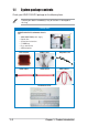
1.1 System package contents Check your ASUS R10-A2P4 package for the following items. Contact your dealer immediately if any of the items is damaged or missing.
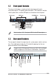
1.2 Front panel features The chassis kit displays a simple yet stylish front panel with easily accessible features. The power and reset buttons, LED indicators, location switch, optical drive, and two USB ports are located on the front panel. Rack screw HDD bays CD-ROM drive Rack screw Power button Power LED Location switch Location LED Reset button USB ports HDD Access LED LAN2 LED LAN1 LED Message LED Refer to section “1.5.1 Front panel LEDs” for the LED descriptions. 1.
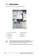
1.4 Internal features The chaais includes the basic components as shown. 2 1 3 4 5 6 7 1. 2. 3. 4. 5. PCI-X riser card bracket Rear fans Power supply Device fan System fans 9 8 6. 7. 8. 9. SATA backplane HDD tray 1 HDD tray 2 Optical drive The chassis kit does not include a floppy disk drive. Connect an external floppy disk drive (USB interface) to any of the USB ports on the front or rear panel if you need to use a floppy disk.
1.5 LED information 1.5.
1-6 Chapter 1: Product introduction
Chapter 2 Hardware setup This chapter lists the hardware setup procedures that you have to perform when installing or removing system components.
2.1 Preparation Before proceeding, prepare everything that you might need to facilitate installation. 2.1.1 Tools to use 1. Phillips head screw driver 2. Flat head screw driver 2.1.2 System components and devices to install The following items are the basics that you need to install into the chassis kit. You may need to install other devices depending on your configuration. 1. 2. 3. 4.
2.2 Removing and installing the chassis cover 2.2.1 Removing the cover 1. Use a Phillips screwdriver to remove the screw on each front end of the top cover. Thumbscrews 2. Loosen the two thumbscrews on the rear panel to release the top cover from the chassis. 3. Firmly hold the cover and slide it toward the rear panel for about half an inch until it is disengaged from the chassis. 1/2 inch distance 4. Lift the cover from the chassis.
2.2.2 Installing the cover 1. Position the cover on top of the chassis with the thumbscrews on the rear, and leaving a gap of about half an inch from the front panel. Side markings 2. Make sure that the side markings on the cover (two on each side) are aligned to the grooves on the chassis. Grooves 3. Slide the cover toward the front until it snaps in place. 4. Tighten the thumbscrews on the rear to secure the cover.
2.3 Motherboard installation This section only describes how to install a supported motherboard into the R10-A2P4 chassis kit. Refer to the motherboard user guide for instructions on installing specific motherboard components. 2.3.1 Motherboard dimensions This chassis kit supports an ASUS motherboard that measures 12 x 10.5 inches (30.48 x 26.67 cm). Motherboards of smaller sizes will fit into the chassis.
2.3.2 Placement direction and screw holes Align the holes on the motherboard (indicated by white circles in the picture below) to the corresponding standoffs on the motherboard metal plate inside the chassis. Place screws through the designated holes to secure the motherboard to the chassis. Refer to the motherboard user guide for the specific number of screws that you need to use.
2.3.3 Installing the motherboard To install the motherboard: 1. Firmly hold the riser card bracket, then pull it up to detach it from the chassis. 2. Clear the motherboard area by re-routing the pre-connected cables to facilitate the motherboard installation. 3. Firmly hold the motherboard as shown, and place the side with the CPU sockets near the system fans.
4. Fit the rear panel connectors to the I/O shield openings on the chassis rear. 5. Match the motherboard holes with the chassis standoffs. 6. Secure the motherboard with screws. Refer to the motherboard user guide for the specific number of screws that you need to use. The chassis appears as shown with the motherboard installed. Refer to the motherboard user guide for instructions on installing CPU, heatsink, and system memory.
2.4 Hard disk drives To install a SATA HDD: 1. Release a drive tray by pushing the spring lock to the right, then pulling the tray lever outward. The drive tray ejects slightly after you pull out the lever. 2. Firmly hold the tray lever and pull the drive tray out of the bay. 3. Take note of the drive tray holes. Each side has three holes to fit different types of hard disk drives. Use two screws on each side to secure the hard disk drive. 4.
5. Carefully insert the drive tray and push it all the way to the depth of the bay until just a small fraction of the tray edge protrudes. SATA interface on the backplane When installed, the SATA connector on the drive connects to the SATA interface on the backplane. 6. Push the tray lever until it clicks, and secures the drive tray in place. The drive tray is correctly placed when its front edge aligns with the bay edge. 7. Repeat steps 1 to 6 if you wish to install a second SATA drive. 8.
2.5 Expansion slot The chassis comes with a riser card bracket. You need to remove the bracket if you wish to install an PCI-X expansion card. To install a PCI-X card: 1. Firmly hold a riser card bracket, then pull it up to detach it from the PCI-X slot on the motherboard. Install a motherboard following the steps in section “2.3.3 Installing a motherboard.” 2. Use a Phillips (cross) screwdriver to remove the screw that secures the slot metal cover. 3.
4. Install the riser card bracket with the card into the PCI-X slot on the motherboard. 5. Make sure that the golden connectors completely fit the slot and the bracket aligns with the rear panel. 6. Connect the cable(s) to the card, if applicable.
2.6 Removable components You may need to remove previously installed system components when installing or removing system devices, or when you need to replace defective components. This section tells how to remove the following components: 1. 2. 3. 4. 5. System fans Device fan Power supply module Optical drive Motherboard 2.6.1 System fans To uninstall the system fans: 1. Disconnect all the system fan cables from the connectors on the backplane board. 2. Remove the four screws that secure a fan. 3.
2.6.3 Power supply module To uninstall the power supply module: 1. Disconnect all the power cables connected to the motherboard and other system devices. 2. Use a Phillips (cross) screwdriver to remove the screw the secures the front end of the power supply. 3. Slide the power supply backward for about half an inch, then carefully lift it out from the chassis.
2.6.4 Optical drive To uninstall the optical drive: 1. Disconnect the power and signal cables connected to the rear of the optical drive. 2. Use a Phillips (cross) screwdriver to remove the two screws that secure the meal bracket on the side of the optical drive. Remove the bracket to release the drive. 3. Slide the optical drive toward the front panel, then carefully pull it out of the drive bay.
To install an optical drive: 1. From the front panel, insert the rear end of the optical drive into the 5.25-inch drive bay. 2. Place the metal bracket parallel to the side of the optical drive, matching its two pegs with the lower holes, and the bracket holes with the standoffs on the base of the chassis. The metal bracket should fit completely to ensure that the optical drive is securely in place.
2.6.5 Motherboard To uninstall the motherboard: 1. Disconnect all the power and signal cables connected to the motherboard. 2. Uninstall all the devices from the motherboard including the CPU and heatsink, riser card brackets, and DDR DIMMs. Refer to the corresponding sections for instructions on removing these components. 3. Use a Phillips (cross) screwdriver to remove the screws that secure the motherboard to the base of the chassis. Refer to the section “2.3.
2.7 SATA backplane cabling (FAN1) Connects the fan cable from CPU_FAN1 on the MB Connects the SMBus cable from the MB Connect the SATA cables from the MB Connect the system fan cables Connect the SATA HDDs Connects a 4-pin plug from power supply Ensure that the FAN1 connector on the SATA backplane and the CPU_FAN2 on the motherboard are connected via the 3-pin fan cable. The fan RPM (rotations per minute) are monitored and automatically adjusted through this feature.
Chapter 3 Rackmounting This chapter tells how to install the system to a rack.
3.1 Rackmount rail kit items If you have the rackmount rail kit, it contains two pairs of rails (one pair for each side of the barebone system), and eight (8) pairs of nut-and-bolt type screws. Nuts Bolts Left pair Right pair 3.2 Rack rails assembly To assemble the rack rails: 1. Determine the depth of the rack where you wish to install the system. 2. Match one long and one short rail to your desired length, and fix them together using four (4) pairs of nuts and bolts. 3.
3.3 Attaching the rails to the rack To attach the rails to the rack: 1. Select one unit of space (1U) on the rack where you wish to install the barebone server. 2. Remove the screws from the 1U space on the rack front. 1U space 3. Align the front end holes of a rack rail pair to the 1U space. 4. Drive in two screws on the outer holes to secure the front end. 5. Find the rear 1U space that corresponds to the front 1U space where you attached the rail. 6.
3.4 Rackmounting the server To mount the server to the rack: 1. Firmly hold the server on both sides and insert the rear panel side to the front end of the rack rail, then carefully push the server all the way to the back until the front panel fits the front end of the rack, and the rack screws on the server match the middle hole on the rack.. 2. Tighten the two rack screws to secure the server to the rack.