Motherboard B85M-E B85M-E/CSM
E9915 Revised Edition v3 November 2014 Copyright © 2014 ASUSTeK COMPUTER INC. All Rights Reserved. No part of this manual, including the products and software described in it, may be reproduced, transmitted, transcribed, stored in a retrieval system, or translated into any language in any form or by any means, except documentation kept by the purchaser for backup purposes, without the express written permission of ASUSTeK COMPUTER INC. (“ASUS”).
Contents Safety information....................................................................................... iv About this guide.......................................................................................... iv Package contents........................................................................................ vi B85M-E specifications summary................................................................ vi Product introduction 1.1 Before you proceed..................................
Safety information Electrical safety • To prevent electrical shock hazard, disconnect the power cable from the electrical outlet before relocating the system. • When adding or removing devices to or from the system, ensure that the power cables for the devices are unplugged before the signal cables are connected. If possible, disconnect all power cables from the existing system before you add a device.
Where to find more information Refer to the following sources for additional information and for product and software updates. 1. ASUS websites The ASUS website provides updated information on ASUS hardware and software products. Refer to the ASUS contact information. 2. Optional documentation Your product package may include optional documentation, such as warranty flyers, that may have been added by your dealer. These documents are not part of the standard package.
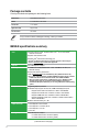
Package contents Check your motherboard package for the following items. Motherboard ASUS B85M-E motherboard Cables 2 x Serial ATA 6.0 Gb/s cables Accessories 1 x I/O Shield Application DVD Support DVD Documentation User Guide If any of the above items is damaged or missing, contact your retailer. B85M-E specifications summary CPU LGA1150 socket for Intel® 4th Generation CoreTM i7/ i5 / i3, Pentium®, Celeron® Processors Supports Intel® 22/32nm CPU Supports Intel® Turbo Boost Technology 2.
B85M-E specifications summary LAN Realtek 8111F Gigabit LAN controller Audio 8-channel Realtek® ALC887-VD2 High Definition Audio CODEC - Supports multi-streaming * Use a chassis with HD audio module in the front panel to support an 8channel audio output. USB 4 x USB 3.0 ports (2 ports at midboard, 2 ports at back panel) 8 x USB 2.0 ports (4 ports at midboard, 4 ports at back panel) ASUS unique features ASUS Exclusive Features: - ASUS USB 3.
B85M-E specifications summary Internal connectors/ switches/ buttons 1 x USB 3.0 connector supports additional 2 USB 3.0 ports 2 x USB 2.0 connectors support additional 4 USB 2.0 ports 2 x SATA 3.0 Gb/s connectors 4 x SATA 6.
Product introduction 1.1 Before you proceed 1 Take note of the following precautions before you install motherboard components or change any motherboard settings. 1.2 • Unplug the power cord from the wall socket before touching any component. • Before handling components, use a grounded wrist strap or touch a safely grounded object or a metal object, such as the power supply case, to avoid damaging them due to static electricity. • Hold components by the edges to avoid touching the ICs on them.
Place this side towards the rear of the chassis B85M-E 1.2.3 Motherboard layout 1 2 3 4 3 5 3 21.3cm(8.4in) KBMS CPU_FAN ASP 1255 ATX12V BATTERY AUDIO B85M-E COM EATXPWR DDR3 DIMM_B2 (64bit, 240-pin module) CHA_FAN1 2 24.4cm(9.
1.2.4 Layout contents Connectors/Jumpers/Slots/LED 1. Serial port connectors (10-1 pin COM) 2. ATX power connectors (24-pin EATXPWR, 4-pin ATX12V) 3. CPU and chassis fan connectors (4-pin CPU_FAN, 4-pin CHA_FAN) 4. Intel® LGA1150 CPU socket 5. DDR3 DIMM slots 6. USB 3.0 connector (20-1 pin USB3_12) 7. Intel® B85 Serial ATA 3.0Gb/s connectors (7-pin SATA3G_1~2 [black]) 8. Intel® B85 Serial ATA 6.0Gb/s connectors (7-pin SATA6G_1~4 [yellow]) 9. System panel connector (10-1 pin F_PANEL) 10.
Unplug all power cables before installing the CPU. 1.3.1 • Upon purchase of the motherboard, ensure that the PnP cap is on the socket and the socket contacts are not bent. Contact your retailer immediately if the PnP cap is missing, or if you see any damage to the PnP cap/socket contacts/motherboard components. ASUS will shoulder the cost of repair only if the damage is shipment/ transit-related. • Keep the cap after installing the motherboard.
4 5 C A B 1.3.2 CPU heatsink and fan assembly installation Apply the Thermal Interface Material to the CPU heatsink and CPU before you install the heatsink and fan if necessary.
To install the CPU heatsink and fan assembly 1 2 A B B A 3 4 To uninstall the CPU heatsink and fan assembly 1 2 A B B A 1-6 Chapter 1: Product introduction
1.4 System memory 1.4.1 Overview DIMM_B1 DIMM_B2 DIMM_A1 DIMM_A2 This motherboard comes with four Double Data Rate 3 (DDR3) Dual Inline Memory Module (DIMM) sockets. A DDR3 module has the same physical dimensions as a DDR2 DIMM but is notched differently to prevent installation on a DDR2 DIMM socket. DDR3 modules are developed for better performance with less power consumption.
1.4.3 • The default memory operation frequency is dependent on its Serial Presence Detect (SPD), which is the standard way of accessing information from a memory module. Under the default state, some memory modules for overclocking may operate at a lower frequency than the vendor-marked value. To operate at the vendor-marked or at a higher frequency, refer to section 2.5 Ai Tweaker menu for manual memory frequency adjustment.
Support the DIMM lightly with your fingers when pressing the retaining clips. The DIMM might get damaged when it flips out with extra force. 2. Remove the DIMM from the socket. 1.5 2 1 DIMM notch Expansion slots In the future, you may need to install expansion cards. The following sub‑sections describe the slots and the expansion cards that they support. Unplug the power cord before adding or removing expansion cards. Failure to do so may cause you physical injury and damage motherboard components.
1.5.3 PCI slot The PCI slots support LAN cards, SCSI cards, USB cards, and other cards that comply with PCI specifications. 1.5.4 PCI Express 2.0 x1 slot This motherboard supports PCI Express x1 network cards, SCSI cards, and other cards that comply with the PCI Express specifications. 1.5.5 PCI Express 3.0/2.0 x16 slot; PCI Express 2.0 x16 (@x4) slot This motherboard supports PCI Express x16 network cards, SCSI cards, and other cards that comply with the PCI Express specifications.
• If the steps above do not help, remove the onboard battery and short the two pins again to clear the CMOS RTC RAM data. After clearing the CMOS, reinstall the battery. • You do not need to clear the RTC when the system hangs due to overclocking. For system failure due to overclocking, use the CPU Parameter Recall (C.P.R.) feature. Shut down and reboot the system, then the BIOS automatically resets parameter settings to default values. 1.7 Connectors 1.7.
Microphone port (pink). This port connects to a microphone. 7. Refer to the audio configuration table for the function of the audio ports in 2.1, 4.1, 5.1, or 7.1-channel configuration. Audio 2.1, 4.1, 5.1, or 7.1-channel configuration Port Light Blue (Rear panel) Lime (Rear panel) Pink (Rear panel) Lime (Front panel) Headset 2.1-channel Line In Line Out Mic In - 4.1-channel Rear Speaker Out Front Speaker Out Mic In - 5.1-channel Rear Speaker Out Front Speaker Out Bass/Center - 7.
1.7.2 1. Internal connectors LPT connector (26-1 pin LPT) The LPT (Line Printing Terminal) connector supports devices such as a printer. LPT standardizes as IEEE 1284, which is the parallel port interface on IBM PC-compatible computers. GND GND GND GND GND GND GND GND SLIN# INIT# ERR# AFD B85M-E PIN 1 SLCT PE BUSY ACK# PD7 PD6 PD5 PD4 PD3 PD2 PD1 PD0 STB# LPT B85M-E Parallel Port Connector 2. ATX power connectors (24-pin EATXPWR, 4-pin ATX12V) These connectors are for ATX power supply plugs.
3. Front panel audio connector (10-1 pin AAFP) NC AGND NC NC SENSE2_RETUR AGND NC SENSE1_RETUR This connector is for a chassis-mounted front panel audio I/O module that supports either HD Audio or legacy AC`97 audio standard. Connect one end of the front panel audio I/O module cable to this connector.
5. CPU and chassis fan connectors (4-pin CPU_FAN, 4-pin CHA_FAN1/2) Connect the fan cables to the fan connectors on the motherboard, ensuring that the black wire of each cable matches the ground pin of the connector. CPU FAN PWM CPU FAN IN CPU FAN PWR GND CPU_FAN B85M-E CHA_FAN2 GND CHA FAN PWR CHA FAN IN +5V CHA_FAN1 GND CHA FAN PWR CHA FAN IN +5V B85M-E Fan connectors Do not forget to connect the fan cables to the fan connectors.
7. Serial port connector (10-1 pin COM) This connector is for a serial (COM) port. Connect the serial port module cable to this connector, then install the module to a slot opening at the back of the system chassis. PIN 1 DCD TXD GND RTS RI RXD DTR DSR CTS COM B85M-E B85M-E Serial port (COM) connector The COM module is purchased separately. 8. Intel® B85 Serial ATA 6.0Gb/s connector (7-pin SATA6G_1~4 [yellow]) This connector connects to Serial ATA 6.0 Gb/s hard disk drives via Serial ATA 6.
9. System panel connector (10-1 pin PANEL) This connector supports several chassis-mounted functions. F_PANEL PLED+ PLEDPWR GND PWR LED PWR BTN HD_LED+ HD_LEDGround HWRST# (NC) PIN 1 B85M-E +HD_LED RESET B85M-E System panel connector • System power LED (2-pin PWR_LED) This 2-pin connector is for the system power LED. Connect the chassis power LED cable to this connector. The system power LED lights up when you turn on the system power, and blinks when the system is in sleep mode.
11. USB 3.0 connector (20-1 pin USB3_12) This connector allows you to connect a USB 3.0 module for additional USB 3.0 front or rear panel ports. With an installed USB 3.0 module, you can enjoy all the benefits of USB 3.0 including faster data transfer speeds of up to 5Gbps, faster charging time for USB-chargeable devices, optimized power efficiency, and backward compatibility with USB 2.0.
13. Chassis intrusion connector (4-1 pin CHASSIS) This connector is for a chassis-mounted intrusion detection sensor or switch. Connect one end of the chassis intrusion sensor or switch cable to this connector. The chassis intrusion sensor or switch sends a high-level signal to this connector when a chassis component is removed or replaced. The signal is then generated as a chassis intrusion event. By default, the pin labeled “Chassis Signal” and “Ground” are shorted with a jumper cap.
1.9 Software support 1.9.1 Installing an operating system This motherboard supports Windows® 7 (32bit/64bit) and Windows® 8 (32bit/64bit) Operating Systems (OS). Always install the latest OS version and corresponding updates to maximize the features of your hardware. Motherboard settings and hardware options vary. Refer to your OS documentation for detailed information. 1.9.
1.9.3 Intel® SBA support Intel® SBA (Small Business Advantage) is a combination of hardware and software that provides unique security and productivity capabilities designed for small businesses. • Intel® SBA requires MEI driver (AMT host software kit) installed. • Some models without the 5MB ME firmware do not support Intel® SBA. Please refer to the spec sheet for details.
BIOS information 2.1 Managing and updating your BIOS 2 Save a copy of the original motherboard BIOS file to a USB flash disk in case you need to restore the BIOS in the future. Copy the original motherboard BIOS using the ASUS Update utility. 2.1.1 EZ Update EZ Update is a utility that allows you to automatically update your motherboard’s softwares, drivers and the BIOS version easily. With this utlity, you can also manually update the saved BIOS and select a boot logo when the system goes into POST.
2.1.2 ASUS EZ Flash 2 The ASUS EZ Flash 2 feature allows you to update the BIOS without using an OS‑based utility. Before you start using this utility, download the latest BIOS file from the ASUS website at www.asus.com. To update the BIOS using EZ Flash 2: 2-2 1. Insert the USB flash disk that contains the latest BIOS file to the USB port. 2. Enter the Advanced Mode of the BIOS setup program. Go to the Tool menu to select ASUS EZ Flash Utility and press to enable it. 3.
2.1.3 ASUS CrashFree BIOS 3 utility The ASUS CrashFree BIOS 3 is an auto recovery tool that allows you to restore the BIOS file when it fails or gets corrupted during the updating process. You can restore a corrupted BIOS file using the motherboard support DVD or a USB flash drive that contains the updated BIOS file. • Before using this utility, rename the BIOS file in the removable device into B85ME.CAP. • The BIOS file in the support DVD may not be the latest version.
Booting the system in DOS environment To boot the system in DOS: 1. Insert the USB flash drive with the latest BIOS file and BIOS Updater to the USB port. 2. Boot your computer then press to launch the select boot device screen. 3. When the select boot device screen appears, insert the Support DVD into the optical drive then select the optical drive as the boot device. Please select boot device: E1: ASUS DVD-E818A6T (4069MB) USB DISK 2.0 (3824MB) UEFI: (FAT) USB DISK 2.
ASUSTeK BIOS Updater for DOS V1.30 [2014/01/01] Current ROM BOARD: B85M-E VER: 0306 (H :00 B :00) DATE: 08/08/2014 PATH: Update ROM BOARD: Unknown VER: Unknown DATE: Unknown C:\ C: D: FORMAN~1 B85ME.CAP
8390656 2014-08-08 21:14:34 Drives panel Files panel Note [Enter] Select or Load [Up/Down/Home/End] Move [Tab] Switch [Esc] Exit [V] Drive Info 3. Press to switch from Drives panel to Files panel then press keys to select the BIOS file and press . 4.2.2 BIOS setup program Use the BIOS Setup program to update the BIOS or configure its parameters. The BIOS screens include navigation keys and brief online help to guide you in using the BIOS Setup program. Entering BIOS Setup at startup To enter BIOS Setup at startup: • Press during the Power-On Self Test (POST). If you do not press , POST continues with its routines. Entering BIOS Setup after POST To enter BIOS Setup after POST: • Press ++ simultaneously.
Displays the CPU/motherboard temperature, CPU voltage output, and CPU/chassis fan speed Selects the Advanced mode functions Selects the boot device priority Power saving mode Selects the display language of the BIOS setup program Exits the BIOS setup program without saving the changes, saves the changes and resets the system, or enters the Advanced Mode Displays the SATA information Normal mode Displays the Advanced mode menus ASUS Optimal mode Loads optimized default Selects the boot device priority
Back button Menu items Menu bar Configuration fields Pop-up window Submenu item General help Navigation keys Scroll bar Menu bar The menu bar on top of the screen has the following main items: Main Ai Tweaker For changing the basic system configuration For changing the overclocking settings Advanced Boot For changing the advanced system settings For displaying the system temperature, power status, and changing the fan settings For changing the system boot configuration Tool Exit For configuri
Pop-up window Select a menu item and press to display a pop-up window with the configuration options for that item. Scroll bar A scroll bar appears on the right side of a menu screen when there are items that do not fit on the screen. Press the Up/Down arrow keys or / keys to display the other items on the screen. Navigation keys At the bottom right corner of the menu screen are the navigation keys for the BIOS setup program.
Adding items to My Favorites To add frequently-used BIOS items to My Favorites: 1. Use the arrow keys to select an item that you want to add. When using a mouse, hover the pointer to the item. 2. Press on your keyboard or right-click on your mouse to add the item to My Favorites page. 2.4 Main menu The Main menu screen appears when you enter the Advanced Mode of the BIOS Setup program.
Administrator Password If you have set an administrator password, we recommend that you enter the administrator password for accessing the system. Otherwise, you might be able to see or change only selected fields in the BIOS setup program. To set an administrator password: 1. Select the Administrator Password item and press . 2. From the Create New Password box, key in a password, then press . 3. Confirm the password when prompted. To change an administrator password: 1.
2.5 Ai Tweaker menu The Ai Tweaker menu items allow you to configure overclocking-related items. Be cautious when changing the settings of the Ai Tweaker menu items. Incorrect field values can cause the system to malfunction. The configuration options for this section vary depending on the CPU and DIMM model you installed on the motherboard.
Target CPU Turbo-Mode Speed : xxxxMHz Displays the target CPU Turbo-Mode speed. Target DRAM Speed : xxxxMHz Displays the target DRAM speed. Target Cache Speed : xxxxMHz Displays the target Cache speed. Target DMI/PEG Clock : xxxxMHz Displays the target DMI/PEG clock. Target CPU Graphics Speed : xxxxMHz Displays the target iGPU speed. 2.5.1 Ai Overclock Tuner [Auto] Allows you to select the CPU overclocking options to achieve the desired CPU internal frequency.
2.5.4 Max. CPU Cache Ratio [Auto] Allows you to set the uncore ratio of the processor to its possible maximum value. The options depend on the CPU installed. 2.5.5 BCLK Frequency: DRAM Frequency Ratio [Auto] Allows you to set the CPU bus speed to DRAM speed ratio mode. [Auto] DRAM speed is set to the optimized settings. [100:133] The BCLK frequency to DRAM speed ratio is set to 100:133. [100:100] The BCLK frequency to DRAM speed ratio is set to 100:100. 2.5.
DRAM RAS# PRE Time [Auto] Configuration options: [Auto] [1 DRAM Clock] – [31 DRAM Clock] DRAM RAS# ACT Time [Auto] Configuration options: [Auto] [1 DRAM Clock] – [63 DRAM Clock] DRAM COMMAND Rate [Auto] Configuration options: [Auto] [1 DRAM Clock] [2 DRAM Clock] Secondary Timings DRAM RAS# to RAS# Delay [Auto] Configuration options: [Auto] [1 DRAM Clock] – [15 DRAM Clock] DRAM REF Cycle Time [Auto] Configuration options: [Auto] [1 DRAM Clock] – [511 DRAM Clock] DRAM Refresh Interval [Auto] Configuration opt
DRAM RTL (CHB_R1D1) [Auto] Configuration options: [Auto] [1 DRAM Clock] – [63 DRAM Clock] DRAM IO-L (CHA_R0D0) [Auto] Configuration options: [Auto] [Delay 1 Clock] - [Delay 15 Clock] DRAM IO-L (CHA_R0D1) [Auto] Configuration options: [Auto] [Delay 1 Clock] - [Delay 15 Clock] DRAM IO-L (CHA_R1D0) [Auto] Configuration options: [Auto] [Delay 1 Clock] - [Delay 15 Clock] DRAM IO-L (CHA_R1D1) [Auto] Configuration options: [Auto] [Delay 1 Clock] - [Delay 15 Clock] DRAM IO-L (CHB_R0D0) [Auto] Configuration options:
tRDWR_dr [Auto] Configuration options: [Auto] [1 DRAM Clock] – [31 DRAM Clock] tRDWR_dd [Auto] Configuration options: [Auto] [1 DRAM Clock] – [31 DRAM Clock] MISC MRC Fast Boot [Enabled] Allows you to enable or disable the MRC fast boot. [Enabled] Enables the MRC fast boot. [Disable] Disables the MRC fast boot. [Auto] Set the MRC fast boot automatically. DRAM CLK Period [Auto] Configuration options: [Auto] [1] – [14] Channel A DIMM Control [Enable Bot...
2.5.11 CPU Power Management The subitems in this menu allow you to set the CPU ratio and features. Enhanced Intel® SpeedStep Technology [Enabled] Allows you to enable or disable the Enhanced Intel® SpeedStep Technology (EIST). [Disabled] Disables this function. [Enabled] The operating system dynamically adjusts the processor voltage and core frequency which may result in decreased average consumption and decreased average heat production.
CPU Internal Power Configuration CPU Integrated VR Efficiency Management [Auto] Allows you to manage the CPU integrated VR efficiency. Configuration options: [Auto] [High Performance] [Balanced] Power Decay Mode [Auto] Enable to improve power saving on the Fully Integrated Voltage Regulator as the processor enters low current mode. Configuration options: [Auto] [Disabled] [Enabled] Idle Power-in Response [Auto] Allows you to set the idle power-in response.
Offset Mode Sign [+] This item appears only when you set the CPU Core Voltage to [Offset Mode] and allows you to set the offset mode sign. Configuration options: [+] [-] CPU Core Voltage Offset [Auto] This item appears only when you set the CPU Core Voltage to [Offset Mode] and allows you to set the CPU core voltage offset. The values range from 0.001V to 0.999V with a 0.001V interval. 2.5.13 CPU Cache Voltage [Auto] This item allows you to set the CPU Cache voltage.
Total Adaptive Mode CPU Graphics Voltage [Auto] This item appears only when you set the CPU Graphics Voltage to [Adaptive Mode] and allows you to set the total adaptive mode CPU graphics voltage. The values range from 0.001V to 1.920V with a 0.001V interval. 2.5.15 CPU System Agent Voltage Offset Mode Sign [+] This item allows you to set the CPU system agent voltage offset mode sign. Configuration options: [+] [-].
2.5.21 DRAM CTRL REF Voltage [Auto] Allows you to set the DRAM CTRL REF Voltage. The values range from 0.3950V to 0.6300V with a 0.0050V interval. 2.5.22 DRAM DATA REF Voltage on CHA [Auto] Allows you to set the DRAM DATA REF Voltage on CHA. The values range from 0.3950V to 0.6300V with a 0.0050V interval 2.5.23 DRAM DATA REF Voltage on CHB [Auto] Allows you to set the DRAM DATA REF Voltage on CHB. The values range from 0.3950V to 0.6300V with a 0.0050V interval 2.5.
2.6 Advanced menu The Advanced menu items allow you to change the settings for the CPU and other system devices. Be cautious when changing the settings of the Advanced menu items. Incorrect field values can cause the system to malfunction. 2.6.1 CPU Configuration The items in this menu show the CPU-related information that the BIOS automatically detects. The items shown in submenu may be different due to the CPU you installed.
Limit CPUID Maximum [Disabled] [Enabled] Allows legacy operating systems to boot even without support for CPUs with extended CPUID functions. [Disabled] Disables this function. Execute Disable Bit [Enabled] [Enabled] Enables the No-Execution Page Protection Technology. [Disabled] Forces the XD feature flag to always return to zero (0).
The following items appear only when you set the CPU C states to [Enabled]. Enhanced C1 state [Enabled] [Enabled] Enables enhanced C1 state. [Disabled] Disables enhanced C1 state. CPU C3 Report [Enabled] Allows you to disable or enable the CPU C3 report to OS. Configuration options: [Enabled] [Disabled] CPU C6 report [Enabled] Allows you to disable or enable the CPU C6 report to OS. Configuration options: [Enabled] [Disabled] C6 Latency [Short] Allows you to choose short or long latency for C6.
Entry on S3 RTC Wake [Enabled] The system automatically wakes up and set to Rapid Start Technology S4 mode. Configuration options: [Enabled] [Disabled Entry After [x] Allows you to set the wake-up time.The values range from 0 (immediately) to 120. Active Page Threshold Support [Enabled] The system automatically set itself to sleep when the partition size is not enough for Rapid Start Technology to work.
S.M.A.R.T. Status Check [Enabled] S.M.A.R.T. (Self-Monitoring, Analysis and Reporting Technology) is a monitor system. When read/write of your hard disk errors occur, this feature allows the hard disk to report warning messages during the POST. Configuration options: [Enabled] [Disabled] Hot Plug [Disabled] These items appear only when you set the SATA Mode Selection item to [AHCI] and allow you to enable/disable SATA Hot Plug Support. Configuration options: [Disabled] [Enabled] 2.6.
NB PCIe Configuration Allows you to configure the NB PCI Express settings. PCIEX16_1 Link Speed [Auto] Allows you to configure the PCIEX16_1 speed. Configuration options: [Auto] [Gen1] [Gen2] [Gen3] DMI Link ASPM Control [Auto] Allows you to enable or disable the control of Active State Power Management on SA side of the DMI Link. Configuration options: [Auto] [Disabled] [L0s] [L1] [L0sL1] PEG - ASPM [Disabled] Allows you to control ASPM support for the PEG Device.
The USB Devices item shows the auto-detected values. If no USB device is detected, the item shows None. Legacy USB Support [Enabled] [Enabled] Enables the support for USB devices on legacy operating systems (OS). [Disabled] The USB devices can be used only for the BIOS setup program. [Auto] Allows the system to detect the presence of USB devices at startup. If detected, the USB controller legacy mode is enabled. If no USB device is detected, the legacy USB support is disabled.
2.6.8 Onboard Devices Configuration HD Audio Controller [Enabled] [Enabled] Enables the HD Audio Device. [Disabled] Disables the HD Audio Device. The following item appears only when you set the HD Audio Controller item to [Enabled]. Front Panel Type [HD] Allows you to set the front panel audio connector (AAFP) mode to legacy AC’97 or highdefinition audio depending on the audio standard that the front panel audio module supports.
Device Mode [STD Printe...] Allows you to select the Printer Port mode. Configuration options: [STD Printer Mode] [SPP Mode] [EPP-1.9 and SPP Mode] [EPP-1.7 and SPP Mode] [ECP Mode] [ECP and EPP 1.9 Mode] [ECP and EPP 1.7 Mode] 2.6.9 APM Deep S4 [Disabled] When enabled, the system in S4 state will further reduce power usage and will power off the USB and PS/2 devices. The system in deep S4 state can be woken up via the power button, devices in LAN, or other ways other than USB and PS/2 devices.
2.6.10 Network Stack Network Stack [Disabled] This item allows user to disable or enable the UEFI network stack. Configuration options: [Disabled] [Enabled] The following two items appear only when you set the previous item to [Enabled]. Ipv4 PXE Support [Enabled] This item allows user to disable or enable the Ipv4 PXE Boot support. Configuration options: [Disable Link] [Enabled] Ipv6 PXE Support [Enabled] This item allows user to disable or enable the Ipv6 PXE Boot support.
2.7.1 CPU Temperature [xxxºC/xxxºF] The onboard hardware monitor automatically detects and displays the CPU temperature. Select Ignore if you do not wish to display the detected temperature. 2.7.2 CPU / Chassis Fan1/2 Speed [xxxx RPM] or [Ignore] / [N/A] The onboard hardware monitor automatically detects and displays the CPU / chassis fan speeds in rotations per minute (RPM). If the fan is not connected to the motherboard, the field shows N/A.
CPU Lower Temperature [20] Displays the lower limit of the CPU temperature. CPU Fan Min. Duty Cycle(%) [20] Use the <+> and <-> keys to adjust the minimum CPU fan duty cycle. The values range from 20% to 100%. When the CPU temperature is under the lower limit, the CPU fan will operate at the minimum duty cycle. 2.7.5 Chassis1/2 Q-Fan Control [Enabled] [Disabled] Disables the Chassis1/2 Q-Fan control feature. [Enabled] Enables the Chassis1/2 Q-Fan control feature.
2.8 Boot menu The Boot menu items allow you to change the system boot options. Scroll down to display the following items: 2.8.1 Fast Boot [Enabled] [Enabled] Select to accelerate the boot speed. [Disabled] Select to go back to normal boot. The following four items appear when you set Fast Boot to [Enabled]. SATA Support [All Devices] [All Devices] All devices connected to SATA ports are available during POST. This process extends the POST time.
USB Support [Partial Initialization] [Disabled] All USB devices will not be available until OS boot up for a fastest POST time. [Full Initialization] All USB devices will be available during POST. This process will extend the POST time. [Partial Initialization] For a faster POST time, only the USB ports with keyboard and mouse connections will be detected. PS/2 Keyboard and Mouse Support [Auto] Select any of these settings when PS/2 keyboard and mouse are installed.
Post Report [5 sec] This item appears only when you set Boot Logo Display to [Disabled]. This item allows you to select a desired post report waiting time. Configuration options: [1 sec] ~ [10 sec] [Until Press ESC]. 2.8.3 Bootup NumLock State [On] [On] Sets the power-on state of the NumLock to [On]. [Off] Sets the power-on state of the NumLock to [Off]. 2.8.4 Wait for ‘F1’ If Error [Enabled] When this item is set to [Enabled], the system waits for the F1 key to be pressed when error occurs.
Boot from Network Devices [Legacy OpROM first] Allows you to select the type of network devices that you want to launch. Configuration options: [Legacy OpROM first] [UEFI driver first] [Ignore] Boot from Storage Devices [Legacy OpROM first] Allows you to select the type of storage devices that you want to launch.
Load PK from File Allows you to load the downloaded PK from a USB storage device. The PK file must be formatted as a UEFI variable structure with time-based authenticated variable. KEK Management The KEK (Key-exchange Key or Key Enrollment Key) manages the Signature database (db) and Revoked Signature database (dbx). Key-exchange Key (KEK) refers to Microsoft® Secure Boot Key-Enrollment Key (KEK). Delete the KEK Allows you to delete the KEK from your system.
Append DBX from file Allows you to load the additional DBX from a storage device so that more db’s images cannot be loaded. The DBX file must be formatted as a UEFI variable structure with time-based authenticated variable. 2.8.10 Boot Option Priorities These items specify the boot device priority sequence from the available devices. The number of device items that appears on the screen depends on the number of devices installed in the system. • • 2.8.
2.9 Tools menu The Tools menu items allow you to configure options for special functions. Select an item then press to display the submenu. 2.9.1 ASUS EZ Flash 2 Utility Allows you to run ASUS EZ Flash 2. Press [Enter] to launch the ASUS EZ Flash 2 screen. For more details, see section 2.1.2 ASUS EZ Flash 2. 2.9.2 ASUS O.C. Profile This item allows you to store or load multiple BIOS settings. The Setup Profile Status items show Not Installed if no profile is created.
2.10 Exit menu The Exit menu items allow you to load the optimal default values for the BIOS items, and save or discard your changes to the BIOS items. You can access the EZ Mode from the Exit menu. Load Optimized Defaults This option allows you to load the default values for each of the parameters on the Setup menus. When you select this option or if you press , a confirmation window appears. Select Yes to load the default values.
Appendices Notices Federal Communications Commission Statement This device complies with Part 15 of the FCC Rules. Operation is subject to the following two conditions: • This device may not cause harmful interference. • This device must accept any interference received including interference that may cause undesired operation. This equipment has been tested and found to comply with the limits for a Class B digital device, pursuant to Part 15 of the FCC Rules.
Canadian Department of Communications Statement This digital apparatus does not exceed the Class B limits for radio noise emissions from digital apparatus set out in the Radio Interference Regulations of the Canadian Department of Communications. This class B digital apparatus complies with Canadian ICES-003. VCCI: Japan Compliance Statement VCCI Class B Statement This is a Class B product based on the standard of the VCCI Council.
ASUS contact information ASUSTeK COMPUTER INC. Address Telephone Fax E-mail Web site 15 Li-Te Road, Peitou, Taipei, Taiwan 11259 +886-2-2894-3447 +886-2-2890-7798 info@asus.com.tw www.asus.com/ Technical Support Telephone Fax Online support +86-21-38429911 +86-21-58668722, ext.9101# http://www.asus.
A-4 Appendices (510)739-3777/(510)608-4555 800 Corporate Way, Fremont, CA 94539. Asus Computer International Date : Signature : Representative Person’s Name : Apr. 18, 2012 Steve Chang / President This device complies with part 15 of the FCC Rules. Operation is subject to the following two conditions: (1) This device may not cause harmful interference, and (2) this device must accept any interference received, including interference that may cause undesired operation.