
User manual


ASUS H170-PRO
1-17
•
Forafullyconguredsystem,werecommendthatyouuseapowersupplyunit
(PSU)thatcomplieswithATX12VSpecication2.0(orlaterversion)andprovidesa
minimumpowerof350W.
•
DONOTforgettoconnectthe4-pin/8-pinATX+12Vpowerplug.Otherwise,the
system will not boot up.
• WerecommendthatyouuseaPSUwithhigherpoweroutputwhenconguringa
systemwithmorepower-consumingdevicesorwhenyouintendtoinstalladditional
devices.Thesystemmaybecomeunstableormaynotbootupifthepoweris
inadequate.
•
Ifyouareuncertainabouttheminimumpowersupplyrequirementforyoursystem,
refertotheRecommendedPowerSupplyWattageCalculatorathttp://support.asus.
com/PowerSupplyCalculator/PSCalculator.aspx?SLanguage=en-us for details.
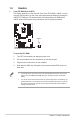
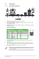
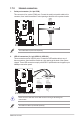
5. ATX power connectors (24-pin EATXPWR, 8-pin ATX12V)
TheseconnectorsareforATXpowersupplyplugs.Thepowersupplyplugsare
designedtottheseconnectorsinonlyoneorientation.Findtheproperorientationand
pushdownrmlyuntiltheconnectorscompletelyt.
H170-PRO
H170-PRO ATX power connectors
EATX12V
+12V DC
+12V DC
+12V DC
+12V DC
GND
GND
GND
GND
EATXPWR
PIN 1
PIN 1
GND
+5 Volts
+5 Volts
+5 Volts
-5 Volts
GND
GND
GND
PSON#
GND
-12 Volts
+3 Volts
+3 Volts
+12 Volts
+12 Volts
+5V Standby
Power OK
GND
+5 Volts
GND
+5 Volts
GND
+3 Volts
+3 Volts
A
A B
B
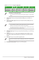
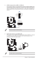
6. TPM connector (14-1 pin TPM)
ThisconnectorsupportsaTrustedPlatformModule(TPM)system,whichsecurely
storekeys,digitalcerticates,passwordsanddata.ATPMsystemalsohelpsenhance
thenetworksecurity,protectsdigitalidentities,andensuresplatformintegrity.
H170-PRO
H170-PRO TPM connector
TPM
PIN 1
+3VSB
S_PCIRST#_TBD
GND
C_PCICLK_TPM
+3V
+3V
F_CLKRUN
F_SERIRQ
F_FRAME#
F_LAD3
F_LAD2
F_LAD1
F_LAD0