
User Guide


ASUS A7A266 User’s Manual 37
3. HARDWARE SETUP
Connectors
3. H/W SETUP
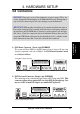
11) Chassis Intrusion Lead (4-1 pin CHASSIS)
This requires an external detection mechanism such as a chassis intrusion monitor/
sensor or microswitch. The sensor is triggered when a high level signal is sent to
the Chassis Signal lead, which occurs when a panel switch or light detector is
triggered. This function works with an optional ASUS CIDB chassis intrusion
module (see your vendor for more details). If the chassis intrusion lead is not
used, a jumper cap must be placed over the pins to close the circuit.
A7A266 Chassis Open Alarm Lead
0 10 1
A7A266
CHASSIS
+5Volt
(Power Supply Stand By)
Ground
Chassis Signal
1
10) IDE Activity LED (2-pin IDELED)
This lead supplies power to the cabinet’s IDE activity LED. Read and write
activity by devices connected to the Primary/Secondary IDE and Primary/
Secondary ATA100 connectors will cause the LED to light up.
0 10 1
A7A266
A7A266 IDE Activity LED
TIP: If the case-mounted LED does not
light, try reversing the 2-pin plug.
IDELED