
User Guide

16
ASUS A7N266 User’s Manual
3. HARDWARE SETUP
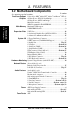
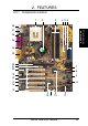
Layout Contents
3. H/W SETUP
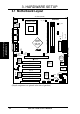
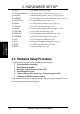
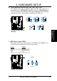
3.3 Hardware Setup Procedure
Complete these procedures before powering up the computer:
1. Check motherboard settings
2. Install memory modules
3. Install the Central Processing Unit (CPU)
4. Install Expansion Cards
5. Connect ribbon cables, panel wires, and power supply cables
6. Configure the BIOS parameter settings
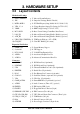
17) SMB p. 39 SMBus Connector (5-1 pin)
18) CD, AUX, MODEM p. 40 Internal Audio Connectors (4-1 pin) (optional)
19) INT_MIC p. 40 Internal Microphone Connector (3 pin) (optional)
20) HPHONE p. 41 Headphone True-level Line Out Header (3-pin) (optional)
21) INT_LINEIN p. 41 Line In Header (3 pin) (optional)
22) S/PDIF p. 42 Digital Audio Interfaces (2 pin) (optional)
23) CHASSIS p. 42 Chassis Open Alarm Lead (4 pin)
24) JTPWR p. 43 Power Supply Thermal Sensor Connector (2 pin)
25) PWR.LED p. 44 System Power LED Lead (3 pin)
26) KEYLOCK p. 44 System Keyboard Lock Switch Lead (2 pin)
27) SPEAKER p. 44 System Warning Speaker Lead (4 pin)
28) LED p. 44 System Message LED Lead (2 pin)
29) SMI p. 44 System Management Interrupt Lead (2 pin)
30) PWR p. 44 ATX / Soft-Off Switch Lead (2 pin)
31) RESET p. 44 Reset Switch Lead (2 pin)
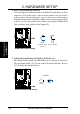
All pertinent information to configure settigns and power up the computer for the
first time appears in the following pages.