
Manual

1-12
Chapter 1: Motherboard Information
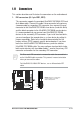
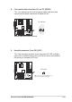
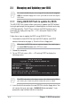
2. Floppy disk drive connector (34-1 pin FLOPPY1)
This connector supports the provided floppy drive ribbon cable. After
connecting one end to the motherboard, connect the other end to the
floppy drive. (Pin 5 is removed to prevent incorrect insertion when
using ribbon cables with pin 5 plug).
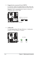
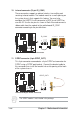
3. OnBoard LED
This Light Emitting Diode (LED) lights-ON if there is standby power
and lights-OFF when the power is turned off.
A7S266-VM
®
NOTE: Orient the red markings on
the floppy ribbon cable to
PIN 1
A7S266-VM Floppy Disk Drive Connector
PIN 1
A7S266-VM
®
A7S266-VM Onboard LED
SB_PWR1
ON
Standby
Power
OFF
Powered
Off