
User guide

ASUS A7V600 Motherboard
1-25
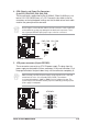
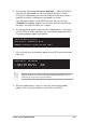
13. System panel connector (20-pin PANEL1)
This connector accommodates several system front panel functions.
A7V600
®
A7V600 System Panel Connectors
* Requires an ATX power supply
.
PLED-
Ground
PWR
+5V
Speaker
Speaker
Connector
Power LED
Ground
Reset SW
SMI Lead
ExtSMI#
Ground
Reset
Ground
Ground
ATX Power
Switch*
PLED+
IDE_LED-
IDE_LED+
IDE_LED
• System Power LED Lead (3-1 pin PLED)
This 3-1 pin connector connects to the system power LED. The LED lights up
when you turn on the system power, and blinks when the system is in sleep
mode.
• System Warning Speaker Lead (4-pin SPKR)
This 4-pin connector connects to the case-mounted speaker and allows you to
hear system beeps and warnings.
• Reset Switch Lead (2-pin RESET)
This 2-pin connector connects to the case-mounted reset switch for rebooting
the system without turning off the system power.
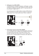
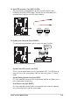
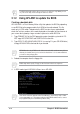
12. Serial ATA connector (7 pin SATA1, SATA2)
These connectors accommodate the primary serial ATA (SATA1) and a
secondary serial ATA (SATA2) cables. Connect the serial ATA cable to this
connector then install to a serial ATA ready hard disk.
A7V600
®
A7V600 SATA Connectors
GND
RSATA_TXP2
RSATA_TXN2
GND
RSATA_RXP2
RSATA_RXN2
GND
SATA1
GND
RSATA_TXP1
RSATA_TXN1
GND
RSATA_RXP1
RSATA_RXN1
GND
SATA2