
Manual


ASUS AP1600R-E2 (CS3)ASUS AP1600R-E2 (CS3)
ASUS AP1600R-E2 (CS3)ASUS AP1600R-E2 (CS3)
ASUS AP1600R-E2 (CS3)
4-34-3
4-34-3
4-3
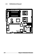
Layout contentsLayout contents
Layout contentsLayout contents
Layout contents
Switches and jumpersSwitches and jumpers
Switches and jumpersSwitches and jumpers
Switches and jumpers
PagePage
PagePage
Page
DIP switch (DSW1) 4-4
SCSI controller setting (3-pin SCSI_EN1) 4-4
Clear RTC RAM (CLRTC1) 4-5
CPU fan pin selection (3-pin FM_CPU1, FM_CPU2) 4-6
USB device wake-up (3-pin USBPW12, USBPW34) 4-6
Keyboard power (3-pin KBPWR1) 4-7
Gigabit LAN1 controller setting (3-pin LAN_EN1) 4-7
Gigabit LAN2 controller setting (3-pin LAN_EN2) 4-8
Integrated graphics controller (3-pin VGA_EN1) 4-8
Force BIOS recovery (3-pin RECOVERY) 4-9
Internal connectorsInternal connectors
Internal connectorsInternal connectors
Internal connectors
PagePage
PagePage
Page
Floppy disk drive connector (34-1 pin FLOPPY) 4-10
IDE connectors (40-1 pin PRI_IDE, SEC_IDE) 4-10
Serial ATA connectors (7-pin SATA1, SATA2) 4-11
Ultra320 SCSI connectors (two 68-pin SCSIA1, SCSIB1) 4-12
Hard disk activity LED connector (4-pin HDLED1) 4-13
CPU and system fan connectors (4-pin CPU_FAN1/2,
3-pin REAR_FAN1/2, FRNT_FAN1/2) 4-13
USB port connector (10-1 pin USB34) 4-14
Serial port connector (10-1 pin COM2) 4-14
SSI power connectors (24-pin ATXPWR1, 8-pin ATX12V1) 4-15
Power supply SMBus connector (5-pin PSUSMB1) 4-16
Backplane SMBus connector (6-1 pin BPSMB1) 4-16
BMC connector (16-pin BMCCONN1) 4-17
Auxiliary panel connector (20-pin AUX_PANEL1) 4-17
Front panel SMB (6-1 pin FPSMB)
LAN activity LED (2-pin 547_LED, 541_LED)
Chassis intrusion (4-1 pin CHASSIS)
Locator LED (6-pin LOCATOR)
System panel connector (20-pin PANEL1) 4-18
System power LED (Green 3-pin PLED)
Message LED (Brown 2-pin MLED)
System warning speaker (Orange 4-pin SPEAKER)
Hard disk drive activity LED (Red 2-pin HDD_LED)
ATX power button/soft-off button (Yellow 2-pin PWRBTN)
Reset button (Blue 2-pin RESET)
Non-maskable interrupt (Light blue 2-pin NMI)