
User Guide


Chapter 4: Motherboard informationChapter 4: Motherboard information
Chapter 4: Motherboard informationChapter 4: Motherboard information
Chapter 4: Motherboard information
4-104-10
4-104-10
4-10
4.3 Internal connectors
This section describes and illustrates the connectors on the motherboard.
See section “1.4 Rear panel features” for the description of rear panel
connectors.
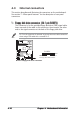
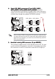
Pin 5 on the connector is removed to prevent incorrect cable connection
when using a FDD cable with a covered Pin 5.
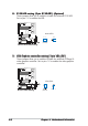
NCLV-D
NOTE: Orient the red markings on
the floppy ribbon cable to PIN 1.
NCLV-D Floppy disk drive connector
PIN 1
FLOPPY
1.1.
1.1.
1.
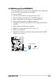
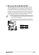
Floppy disk drive connector (34-1 pin FLOPPY)Floppy disk drive connector (34-1 pin FLOPPY)
Floppy disk drive connector (34-1 pin FLOPPY)Floppy disk drive connector (34-1 pin FLOPPY)
Floppy disk drive connector (34-1 pin FLOPPY)
This connector is for the provided floppy disk drive (FDD) signal cable.
Insert one end of the cable to this connector, then connect the other
end to the signal connector at the back of the floppy disk drive.