® Vintage-PE2 Barebone System Quick Installation Guide
Front panel features N O T E . The photos in this guide are for reference only. For detailed information on your system’s specifications, refer to the user guide. External Internal 5.25-inch bays (drive not included) HDD bay FDD bay (drive not included) Reset button HDD LED Power button USB 2.0 ports Microphone port Headphone port Rear panel features Power socket Voltage selector Power supply module PS/2 keyboard port PS/2 mouse port Parallel port VGA port Chassis fan vent USB 2.0 ports USB 2.
Voltage selector The switching power supply that came with the system has a voltage selector switch below the power socket. Use this switch to select the appropriate voltage according to the voltage supply in your area. If the voltage supply in your area is 100-127 V, set the switch to 115 V. If the voltage supply in your area is 200-240 V, set the switch to 230 V. 115 V/230 V Voltage selector C A U T I O N .
Removing the side plate and front cover 1 2 Screw Remove the two screws on the rear panel. 3 I M P O R T A N T . Repeat steps 1 and 2 to remove the other side plate. 4 Side lock tab Release the side lock tabs. Hinge-like tab Swing the left edge of the front panel outward, then unhook the hinge-like tabs from the holes on the right side of the front panel.
Installing a CPU 1. Press the load lever with your thumb. 2. 1 Move it to the left until it is released from the retention tab. 2 C A U T I O N . To prevent damage to the socket pins, do not remove the PnP cap unless you are installing a CPU. 5 3 4 7 6 8 Alignment key Gold triangle mark 9 Installing system memory C A U T I O N . A DDR DIMM is keyed with a notch so that it fits in only one direction. DO NOT force a DIMM into a socket to avoid damaging the DIMM.
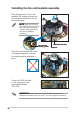
Installing the fan and heatsink assembly Place the heatsink on top of the installed CPU, making sure that the four fasteners match the holes on the motherboard. 1 N O T E . Make sure to orient each fastener with the narrow end of the groove pointing outward. (The photo shows the groove shaded for emphasis.) Narrow end of the groove Push down two fasteners at a time in a diagonal sequence to secure the heatsink and fan assembly in place.
Installing an optical drive 2 1 1 Remove the drive bay plate cover. 3 4 Audio cable IDE ribbon cable Red stripe to Pin 1 Power cable Installing a hard disk drive 2 2 1 3 Connect the blue interface of the IDE ribbon cable to the primary IDE connector (blue connector labeled PRI_IDE1) on the motherboard.
Replacing the side plate and front cover 2 1 Hinge-like tab 3 Side lock tab Snap the side lock tabs to secure the front panel. 4 Screw Drive in two screws on the rear panel. I M P O R T A N T . Repeat steps 3 and 4 to replace the other side plate.