® Technical Publications GS-1530 GS-1930 Service Manual (before serial number 17408) First Edition, Third Printing Rev C2 Part No.
Introduction Service Manual - First Edition GS-1530 GS-1930 Genie North America Important Read, understand and obey the safety rules and operating instructions in the appropriate Genie GS-1530 & Genie GS-1930 Operator’s Manual before attempting any maintenance or repair procedure. This manual provides detailed scheduled maintenance information for the machine owner and user. It also provides troubleshooting and repair procedures for qualified service professionals.
Service Manual - First Edition Safety Rules Danger Failure to obey the instructions and safety rules in this manual and the appropriate Genie GS-1530 & Genie GS-1930 Operator’s Manual will result in death or serious injury. Many of the hazards identified in the operator’s manual are also safety hazards when maintenance and repair procedures are performed. Do Not Perform Maintenance Unless: You are trained and qualified to perform maintenance on this machine.
Service Manual - First Edition SAFETY RULES protective clothing if the situation warrants it. Personal Safety Any person working on or around a machine must be aware of all known safety hazards. Personal safety and the continued safe operation of the machine should be your top priority. Read each procedure thoroughly. This manual and the decals on the machine use signal words to identify the following: Safety alert symbol—used to alert personnel to potential personal injury hazards.
Service Manual - First Edition Theory of Operation Power Source The Genie GS-1530 and GS-1930 machines are powered by four six-volt (255 AH) batteries. The four batteries are wired in series to produce 24 volts. Hydraulic System All machine functions are performed by the hydraulic system. The hydraulic system is powered by a single-section gear pump. When the pump is activated, it supplies hydraulic fluid under pressure to the function manifold, where the control valves are located.
Service Manual - First Edition Table of Contents Introduction Important Information ...................................................................................................... ii Section One Safety Rules General Safety Rules ..................................................................................................... iii Theory of Operation .......................................................................................................
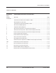
Service Manual - First Edition TABLE OF CONTENTS Section Four Scheduled Maintenance Procedures, continued B-1 Check the Batteries ......................................................................................... 4 - 8 B-2 Inspect the Electrical Wiring ............................................................................ 4 - 9 B-3 Inspect the Tires and Wheels (including castle nut torque) ........................... 4 - 10 B-4 Test the Key Switch .....................................
Service Manual - First Edition TABLE OF CONTENTS Section Five Troubleshooting Flow Charts and Fault Codes Chart Number Chart Title Page Introduction ............................................................................................................................................ 5 - 1 Fault Code Chart Before Serial Number 17408 ........................................................ 5 - 3 Normal Operation Code Chart ..........................................................................
Service Manual - First Edition TABLE OF CONTENTS Section Six Schematics Introduction ............................................................................................................... 6 - 1 Electrical Components .............................................................................................. 6 - 2 Module Tray Legend ................................................................................................. 6 - 3 Electrical Symbols Legend ..................................
Service Manual - First Edition TABLE OF CONTENTS Section Seven Repair Procedures Introduction ............................................................................................................... 7 - 1 Platform Controls 1-1 Platform Controller .......................................................................................... 7 - 2 1-2 Software Configuration .................................................................................... 7 - 3 1-3 Toggle Switches ...............
Service Manual - First Edition Section 2 - Specifications Specifications REV D Machine Specifications Model Operational dimensions GS-1530 GS-1930 Stowed dimensions Length Maximum platform height 15 ft 4.6 m 19 ft 5.8 m Maximum platform working height 21 ft 6.4 m 25.1 ft 7.7 m 391/4 in 1m 391/4 in 1m Wheelbase 52 in 132.1 cm 52 in 132.1cm Turning raduis, outside 61 in 154.9 cm 61 in 154.9 cm 0 in 0 cm 0 in 0 cm 72 in 183 cm 72 in 183 cm 1011/2 in 257.8 cm 1011/2 in 257.
Section 2 - Specifications Service Manual - First Edition SPECIFICATIONS REV D Performance Specifications Model GS-1530 Hydraulic Specifications GS-1930 Drive speeds (maximum) Stowed, maximum Platform raised, maximum 4 km/h 12.2 m / 10.7 sec 0.5 mph 40 ft / 55 sec 0.7 km/h 12.2 m / 55 sec 2-2 Type: gear Displacement per revolution .244 cu in 4 cc Displacement 4 gallons per minute 15 liters per minute (2500 psi/172 bar) Hydraulic tank return line filter 10 micron with 25 psi (1.
Service Manual - First Edition Section 2 - Specifications REV D SPECIFICATIONS Hydraulic Hose and Fitting Torque Specifications Your machine is equipped with either 37° flared fittings and hose ends OR Parker Seal-Lok® fittings and hose ends. Machines that utilize Parker Seal-Lok® hoses and fittings require that the fittings and hose ends be torqued to specification when they are removed and installed or when new hoses or fittings are installed.
Section 2 - Specifications Service Manual - First Edition This page intentionally left blank. 2-4 Genie GS-1530 & Genie GS-1930 Part No.
Service Manual - First Edition Section 3 - Scheduled Maintenance Inspections Scheduled Maintenance Inspections Dealer About This Section Tools are New parts required required The Schedule Observe and Obey: Maintenance inspections shall be completed by a person trained and qualified on the maintenance of this machine. Scheduled maintenance inspections shall be completed daily, quarterly, annually and every 2 years as specified on the Maintenance Inspection Report.
Section 3 - Scheduled Maintenance Inspections Service Manual - First Edition Maintenance Tables Table A Tools are required A-1 Inspect the Operator's and Safety Manuals A-2 Inspect the Decals and Placards A-3 Inspect for Damage, Loose or Missing Parts A-4 Check the Hydraulic Oil Level A-5 Check for Hydraulic Leaks A-6 Test the Platform and Ground Controls A-7 Test the Manual Platform Lowering Operation A-8 Test the Tilt Sensor A-9 Test the Pothole Guards A-10 Test the Lift/Drive Selec
Service Manual - First Edition Section 3 - Scheduled Maintenance Inspections MAINTENANCE TABLES Table B, continued Tools are required B-5 Test the Emergency Stop Buttons B-6 Test the Horn B-7 Test the Drive Brakes B-8 Test the Drive Speed - Stowed Position B-9 Test the Drive Speed - Raised Position B-10 Perform Hydraulic Oil Analysis See D-1 Test or Replace the Hydraulic Oil B-11 Check the Electrical Contactor (before serial number 6901) New parts required Dealer service suggested Table
Section 3 - Scheduled Maintenance Inspections Service Manual - First Edition Maintenance Inspection Report Model Checklist A Serial number Date Hour meter Machine owner Refer to Table A New parts required Checklist C Y N R Dealer Refer toservice Table C suggested C-6 Hydraulic filter A-1 Operator's and Safety manuals A-2 Decals and placards Checklist D A-3 Damage, loose or missing parts Refer to Table D Y N R D-1 Hydraulic oil A-4 Hydraulic oil level Inspected by (print) A-5 Hydraulic lea
Service Manual - First Edition Section 4 - Scheduled Maintenance Procedures Scheduled Maintenance Procedures About This Section This section contains detailed procedures for each scheduled maintenance inspection. Each procedure includes a description, safety warnings and step-by-step instructions. Observe and Obey: Symbols Legend Safety alert symbol—used to alert personnel to potential personal injury hazards. Obey all safety messages that follow this symbol to avoid possible injury or death.
Section 4 - Scheduled Maintenance Procedures Service Manual - First Edition Table A Procedures A-1 Inspect the Operator’s and Safety Manuals A-2 Inspect the Decals and Placards Maintaining the operator’s and safety manuals in good condition is essential to safe machine operation. Manuals are included with each machine and should be stored in the container provided in the platform. An illegible or missing manual will not provide safety and operational information necessary for a safe operating condition.
Service Manual - First Edition Section 4 - Scheduled Maintenance Procedures TABLE A A-3 Inspect for Damage and Loose or Missing Parts Daily machine condition inspections are essential to safe machine operation and good machine performance. Failure to locate and repair damage, and discover loose or missing parts may result in an unsafe operating condition. A-4 Check the Hydraulic Oil Level Maintaining the hydraulic oil at the proper level is essential to machine operation.
Section 4 - Scheduled Maintenance Procedures TABLE A Service Manual - First Edition PROCEDURES A-5 Check for Hydraulic Leaks Detecting hydraulic fluid leaks is essential to operational safety and good machine performance. Undiscovered leaks can develop into hazardous situations, impair machine functions and damage machine components.
Service Manual - First Edition Section 4 - Scheduled Maintenance Procedures TABLE A 8 Slowly move the control handle in the direction indicated by the blue arrow. Result: The platform should raise. The pothole guards should deploy. 9 Release the control handle. Result: The platform should stop raising. 10 Press and hold the function enable switch. Slowly move the control handle in the direction indicated by the yellow arrow. Result: The platform should lower.
Section 4 - Scheduled Maintenance Procedures TABLE A Service Manual - First Edition PROCEDURES A-8 Test the Tilt Sensor A-9 Test the Pothole Guards Perform this test from the ground with the platform controls. Do not stand in the platform. The pothole guards should automatically deploy when the platform is raised. The pothole guards activate two limit switches which control the machine drive speed. If the pothole guards do not deploy and the platform is raised above 6 feet (1.
Service Manual - First Edition Section 4 - Scheduled Maintenance Procedures TABLE A PROCEDURES A-10 Test the Lift/Drive Select Switch (before serial number 17408) A properly functioning Lift/Drive Select Switch is essential for safe machine operation. An improperly operating Lift/Drive Select Switch will fail to activate the appropriate platform control which may result in a hazardous situation.
Section 4 - Scheduled Maintenance Procedures Service Manual - First Edition Table B Procedures 7 Check each battery pack and verify that the batteries are wired correctly. B-1 Check the Batteries Proper battery condition is essential to good machine performance and operational safety. Improper fluid levels or damaged cables and connections can result in component damage and hazardous conditions. Bodily injury hazard. Batteries contain acid. Avoid spilling or contacting battery acid.
Service Manual - First Edition Section 4 - Scheduled Maintenance Procedures TABLE B PROCEDURES B-2 Inspect the Electrical Wiring Maintaining electrical wiring in good condition is essential to safe operation and good machine performance. Failure to find and replace burnt, chafed, corroded or pinched wires could result in unsafe operating conditions and may cause component damage. Electrocution hazard. Contact with hot or live circuits may result in death or serious injury.
Section 4 - Scheduled Maintenance Procedures TABLE B Service Manual - First Edition PROCEDURES B-3 Inspect the Tires and Wheels (including castle nut torque) B-4 Test the Key Switch Maintaining the tires and wheels in good condition is essential to safe operation and good performance. Tire and/or wheel failure could result in a machine tip-over. Component damage may also result if problems are not discovered and repaired in a timely fashion.
Service Manual - First Edition Section 4 - Scheduled Maintenance Procedures TABLE B PROCEDURES B-5 Test the Emergency Stop Buttons B-6 Test the Horn Properly functioning Emergency Stop buttons are essential for safe machine operation. An improperly operating Emergency Stop button will fail to shut off power and stop all machine functions resulting in a hazardous situation. A functioning horn is essential to safe machine operation.
Section 4 - Scheduled Maintenance Procedures Service Manual - First Edition TABLE B PROCEDURES B-7 Test the Drive Brakes 7 Measure the distance between the test line and your machine reference point. Proper brake action is essential to safe machine operation. The drive brake function should operate smoothly, free of hesitation, jerking and unusual noise. Hydraulically-released individual wheel brakes can appear to operate normally when not fully operational.
Service Manual - First Edition Section 4 - Scheduled Maintenance Procedures TABLE B PROCEDURES 10 Tag the forward and the reverse valve coils. Remove the coils from the valve. The forward valve coil has white and brown wires attached. The reverse valve coil has white/black and brown wires attached. For reassembly, it will be helpful to leave the wire harness attached to the valve coils. 11 Remove the drive forward/reverse valve from the function manifold. Cap the open port of the manifold.
Section 4 - Scheduled Maintenance Procedures Service Manual - First Edition TABLE B PROCEDURES B-8 Test the Drive Speed Stowed Position B-9 Test the Drive Speed Raised Position Proper drive functions are essential to safe machine operation. The drive function should respond quickly and smoothly to operator control. Drive performance should also be free of hesitation, jerking and unusual noise over the entire proportionally controlled speed range.
Service Manual - First Edition Section 4 - Scheduled Maintenance Procedures TABLE B PROCEDURES B-10 Perform Hydraulic Oil Analysis See D-1, Test or Replace the Hydraulic Oil. B-11 Check the Electrical Contactor (before serial number 6901) Maintaining the electrical contactor in good condition is essential to safe machine operation. Failure to locate a worn or damaged contactor could result in an unsafe working condition and component damage.
Section 4 - Scheduled Maintenance Procedures Service Manual - First Edition Table C Procedure C-1 Replace the Hydraulic Filter Replacement of the hydraulic filter is essential for good machine performance and service life. A dirty or clogged filter may cause the machine to perform poorly and continued use may cause component damage. Extremely dirty conditions may require that the filter be replaced more often. Beware of hot oil. Contact with hot oil may cause severe burns.
Service Manual - First Edition Section 4 - Scheduled Maintenance Procedures Table D Procedure D-1 Test or Replace the Hydraulic Oil 6 Remove the motor controller mounting bracket retaining fasteners and move the motor controller to the side. Replacement or testing of the hydraulic oil is essential for good machine performance and service life. Dirty oil and suction strainer may cause the machine to perform poorly and continued use may cause component damage.
Section 4 - Scheduled Maintenance Procedures Service Manual - First Edition This page intentionally left blank. 4 - 18 Genie GS-1530 & Genie GS-1930 Part No.
Section 5 - Troubleshooting Flow Charts Service Manual - First Edition Troubleshooting Flow Charts Before Troubleshooting: Read, understand and obey the safety rules and operating instructions printed in the Genie GS-1530 & Genie GS-1930 Operator’s Manual. Be sure that all necessary tools and test equipment are available and ready for use. Observe and Obey: Troubleshooting and repair procedures shall be completed by a person trained and qualified on the repair of this machine.
Section 5 - Troubleshooting Flow Charts Service Manual - First Edition TROUBLESHOOTING FLOW CHARTS General Repair Process About This Section When a malfunction is discovered, the flow charts in this section will help a service professional pinpoint the cause of the problem. To use this section, basic hand tools and certain pieces of test equipment are required—voltmeter, ohmmeter, pressure gauges.
Section 5 - Troubleshooting Flow Charts Service Manual - First Edition Fault Code Chart (Before Serial Number 17408) Fault Code Problem Possible Causes Solution Reset the ECM. If problem remains, replace the ECM. 00 18 Alarm sounds continuously. Error indicator light on at the platform controls when function enable switch is engaged. Machine will not drive. Machine is not level. Pothole guard may be blocked or pothole limit switches may not be activating or there is a bad wire connection.
Section 5 - Troubleshooting Flow Charts Service Manual - First Edition FAULT CODE CHART (BEFORE SERIAL NUMBER 17408) Fault Code Problem Possible Causes Solution 52 Machine will not drive forward. Pump motor starts. Error No power output from ECM to indicator light on at the platform the drive forward coil. controls when the function enable switch is engaged. 53 Machine will not drive in reverse. Pump motor starts.
Section 5 - Troubleshooting Flow Charts Service Manual - First Edition FAULT CODE CHART (BEFORE SERIAL NUMBER 17408) Fault Code Problem Possible Causes 60 Machine will not operate. Error Lift/drive switch is turned "off" indicator light on at the platform or in a neutral position. controls. 63 Machine will not operate. Flashing green LED at the platform controls. 88 Machine will not operate. ECM EPROM not programmed. cannot be reset. Solution Check switch position OR Replace switch.
Section 5 - Troubleshooting Flow Charts Service Manual - First Edition Normal Operation Code Chart (Before Serial Number 17408) Code 20 flashing 21 flashing 22 flashing 23 flashing 24 flashing 25 flashing 31 flashing 32 flashing 36 flashing 37 flashing 38 flashing 39 flashing 40 flashing 5-6 Condition Explanation Key switch to platform control. Platform extended above 6 feet. Ground control and platform Emergency Stop buttons pulled out to the on position.
Service Manual - First Edition Section 5 - Troubleshooting Flow Charts This page intentionally left blank. Part No.
Section 5 - Troubleshooting Flow Charts Service Manual - First Edition Fault Code Chart (After Serial Number 17407) Fault Code 01 02 03 12 18 42 43 45 46 47 52 53 54 55 56 57 58 68 Problem Possible Causes Solution Machine will not operate. ECM EPROM not programmed. cannot be reset. Replace ECM. Platform ECM error. Replace ECM. EPROM not programmed. Undefined platform DIP switch DIP switch settings incorrect. settings. Chassis up/down switch closed Malfunctioningup/down switch. at start up.
Section 5 - Troubleshooting Flow Charts Service Manual - First Edition Chart 1 All Functions Will Not Operate Be sure the circuit breaker and fuse are not tripped or blown. Be sure the batteries are properly connected. Be sure the batteries are fully charged. Be sure both Emergency Stop switches are pulled out to the ON position. Turn keyswitch to platform control and press and hold the function enable switch. Visually inspect the power-on LED.
Section 5 - Troubleshooting Flow Charts Service Manual - First Edition CHART 1 Continued from the previous page. After serial number 6901: Check voltage at input side of 7A circuit breaker F2. Before serial number 6900:(wire 24F- circuit breaker to relay). 0V 24V Check voltage at wht wire at input side of Emergency Stop Switch S1. 0V Before serial number 6900:Repair open in wht wire from input side of motor contactor to input side of 7A circuit breaker (24f-circuit breaker to relay).
Section 5 - Troubleshooting Flow Charts Service Manual - First Edition CHART 1 Continued from the previous page. Turn key switch to platform control position and check output side of each contact. 0V Check cam on key switch. bad Repair or replace key switch. good 24V Replace bad contact OR refer to Platform Controls Inoperative, Chart 6 OR consult the Genie Industries Service Department.
Section 5 - Troubleshooting Flow Charts Service Manual - First Edition Chart 2 Pump Motor Will Not Operate Activate lift function from the ground controls and check voltage at positive terminal on pump motor. 24V or more Check voltage on B+ terminal on motor controller. less than Replace positive battery 24V cable from pump to B+ terminal on motor controller. 24V no continuity Replace ground cable Check continuity on ground cable from pump on lift pump motor. motor to M- terminal on controller.
Section 5 - Troubleshooting Flow Charts Service Manual - First Edition CHART 2 Continued from the previous page. Activate lift function and check voltage on the output side of PR1. 24V or more Replace positive cable from PR1 to Curtis controller OR replace positive cable from curtis controller to pump motor. 24V or more Activate lift function and check voltage on the white wire on the coil of K1. less than 24V Activate lift function and check voltage on the input side of K1.
Section 5 - Troubleshooting Flow Charts Service Manual - First Edition Chart 3 All Functions Inoperative, Power Unit Starts and Runs Be sure, if the Error Indicator light is on at the platform controls, you refer to the specific chart that relates to the error code that is displayed on the ECM. Be sure the circuit breaker and fuse are not tripped or blown. Be sure the batteries are properly connected. Check hydraulic fluid level. low Fill with Dexron II equivalent hydraulic fluid.
Section 5 - Troubleshooting Flow Charts Service Manual - First Edition Chart 4 Ground Controls Inoperative, Platform Controls Operate Normally With key switch in ground position and the Emergency Stop buttons pulled out to the ON position at both the ground and platform controls, check voltage on the contact at the input side of the key switch at the ground controls (S2). 0V Repair open in wht wire jumper from the platform control contact to the ground control contact at the key switch (S2).
Section 5 - Troubleshooting Flow Charts Service Manual - First Edition Chart 5 Platform Controls Inoperative, Ground Controls Operate Normally Turn the key switch to platform control and make sure both Emergency Stop buttons are pulled out to the ON position at both the ground and platform controls. Check voltage at the input side of the platform controls contact on the key switch (S2).
Section 5 - Troubleshooting Flow Charts Service Manual - First Edition CHART 5 Continued from the previous page. Before serial number 6091: Check voltage at the input side of the Emergency Stop switch at the platform controls. 0V Replace the main circuit board. 0V Replace contact on Emergency Stop switch OR replace Emergency Stop switch. 24V Check voltage at output side of platform Emergency Stop switch. 24V Check voltage at terminal 5 on the main circuit board at the platform controls.
Section 5 - Troubleshooting Flow Charts Service Manual - First Edition Chart 6 Platform Up Function Inoperative Be sure all other functions operate normally. With the key switch in platform position and both Emergency Stop buttons pulled out to the ON position and the lift/ drive selector switch in the lift position, activate the controller in the UP direction and check to see if the error indicator light at the platform controls is on.
Section 5 - Troubleshooting Flow Charts Service Manual - First Edition Chart 7 Platform Down Function Inoperative Be sure all other functions operate normally. Be sure the circuit breaker and fuse are not tripped or blown.
Section 5 - Troubleshooting Flow Charts Service Manual - First Edition CHART 7 Continued from the previous page. Label and disconnect the wires from the lift/ drive toggle switch at the platform controls and troubleshoot the toggle switch (see Repair Section). switch bad Replace the lift/drive toggle switch. good Replace the platform controls OR replace the ECM OR consult the Genie Industries Service Department. 5 - 20 Genie GS-1530 & Genie GS-1930 Part No.
Section 5 - Troubleshooting Flow Charts Service Manual - First Edition Chart 8 Steer Left Function Inoperative Be sure all other functions operate normally. With the key switch in platform position and both Emergency Stop buttons pulled out to the ON position, activate the steer rocker switch in the LEFT direction and check to see if the error indicator light at the platform controls is on. light is on Be sure the circuit breaker and fuse are not tripped or blown.
Section 5 - Troubleshooting Flow Charts Service Manual - First Edition CHART 8 Continued from the previous page. Install a 0 to 2000 psi pressure gauge at the quick disconnect coupling on the function manifold and activate the steer left function. less than 1200 psi 1200 psi Check for mechanical restrictions keeping the steer left function from moving OR repair or replace the steer cylinder OR consult the Genie Industries Service Department.
Section 5 - Troubleshooting Flow Charts Service Manual - First Edition Chart 9 Steer Right Function Inoperative Be sure all other functions operate normally. With the key switch in platform position and both Emergency Stop buttons pulled out to the ON position, activate the steer rocker switch in the LEFT direction and check to see if the error indicator light at the platform controls is on. light is on Be sure the circuit breaker and fuse are not tripped or blown.
Section 5 - Troubleshooting Flow Charts Service Manual - First Edition CHART 9 Continued from the previous page. Install a 0 to 2000 psi pressure gauge at the quick disconnect coupling on the function manifold and activate the steer right function. less than 1200 psi 1200 psi Check for mechanical restrictions keeping the steer right function from moving OR repair or replace the steer cylinder OR consult the Genie Industries Service Department.
Section 5 - Troubleshooting Flow Charts Service Manual - First Edition Chart 10 All Drive Functions Inoperative, All Other Functions Operate Normally Be sure, if the Error Indicator light is on at the platform controls, you refer to the specific chart that relates to the error code that is displayed on the ECM. Be sure the circuit breaker and fuse are not tripped or blown.
Section 5 - Troubleshooting Flow Charts Service Manual - First Edition CHART 10 Continued from the previous page. See Chart 3. Is the coupler between the motor and pump in good condition? no Replace or repair coupler, motor, and/or pump. yes 3000 psi Chock both sides of the or more front drive wheels. Connect a 0 to 5000 psi (0 to 345 bar) pressure gauge to the test port on the function manifold and drive the machine in either the forward or reverse direction.
Section 5 - Troubleshooting Flow Charts Service Manual - First Edition Chart 10A Brake Release Function Inoperative Be sure, if the Error Indicator light is on at the platform controls, you refer to the specific chart that relates to the error code that is displayed on the ECM. Chock the wheels at the steer end. Jack the non steer end of the machine up approximately 4 inches (10 cm) and place jack stands under the machine for support.
Section 5 - Troubleshooting Flow Charts Service Manual - First Edition Chart 11 Drive Forward Function Inoperative Be sure all other functions operate normally. With the key switch in platform position and the Emergency Stop buttons pulled out to the ON position at both the ground and platform controls, activate drive controller in the forward direction and check to see if the error indicator light at the platform controls is on. Be sure the circuit breaker and fuse are not tripped or blown.
Section 5 - Troubleshooting Flow Charts Service Manual - First Edition Chart 12 Drive Reverse Function Inoperative Be sure all other functions operate normally. With the key switch in platform position and the Emergency Stop buttons pulled out to the ON position at both the ground and platform controls, activate the drive controller in the reverse direction and check to see if the error indicator light at the platform controls is on. Be sure the circuit breaker and fuse are not tripped or blown.
Section 5 - Troubleshooting Flow Charts Service Manual - First Edition Chart 13 Machine Will Not Drive At Full Speed Be sure the circuit breaker and fuse are not tripped or blown. Be sure the batteries are properly connected. Be sure the batteries are fully charged. With the key switch in platform position and the Emergency Stop buttons pulled out to the ON position at both the ground and platform controls, and the platform in the stowed position, drive the machine in either direction.
Section 5 - Troubleshooting Flow Charts Service Manual - First Edition CHART 13 Continued from the previous page. Repair open in the wht wire (B10-pothole switch) from the output side of S6 to the ECM OR replace the ECM. Chock both sides of the front drive wheels. less Install a 0 to 5000 psi than (0 to 345 bar) pressure 3000 psi gauge to the test port on the function manifold and drive the machine in either the forward or reverse direction.
Section 5 - Troubleshooting Flow Charts Service Manual - First Edition Chart 14 Machine Drives At Full Speed With Platform Raised Be sure the circuit breaker and fuse are not tripped or blown. Be sure the batteries are properly connected. With the key switch in platform position and the Emergency Stop buttons pulled out to the ON position at both the ground and platform controls, and the platform in the stowed position, drive the machine in either direction.
Service Manual - First Edition Section 6 - Schematics Schematics About This Section There are two groups of schematics in this section. An illustration legend precedes each group of drawings. Electrical Schematics Observe and Obey: Electrocution hazard. Contact with electrically charged circuits may result in death or serious injury. Remove all rings, watches and other jewelry. Troubleshooting and repair procedures shall be completed by a person trained and qualified on the repair of this machine.
Section 6 - Schematics Service Manual - First Edition Electrical Components Item Description Genie Part Part Number Manufacturer Manufacturer Part Number Qty AP1 ................ Anderson connector ............ 19436 ............. Anderson ............................. 6325-G1 ......................... 2 B1 ................... Alarm, steady tone .............. 39540 ............. Floyd Bell Inc. ...................... UC-09628-Q .................. 1 B2 ................... Alarm, intermittent ......
Service Manual - First Edition Section 6 - Schematics Module Tray Legend Module Tray Legend (models before serial number 6901) Module Tray Legend (models after serial number 6900) Part No.
Section 6 - Schematics Service Manual - First Edition Electrical Symbols Legend 6-4 Genie GS-1530 & Genie GS-1930 Part No.
Service Manual Section 6 - Schematics Electrical Schematic (models before serial number 6901) A B C 1 2 3 4 5 6 7 8 6-5 Genie GS-1530 & GS-1930 Part No.
Service Manual Section 6 - Schematics Electrical Schematic (models before serial number 6901) N M L K J I H G F E D C B A 1 2 3 4 5 6 7 8 Part No.
Service Manual Section 6 - Schematics Electrical Schematic (models before serial number 6901)
Service Manual Section 6 - Schematics Electrical Schematic (models from serial number 6901 to 8931) A B C D 1 2 3 4 5 6 7 8 6-7 Genie GS-1530 & GS-1930 Part No.
Service Manual Section 6 - Schematics Electrical Schematic (models from serial number 6901 to 8931) N M L K J I H G F E D C B A 1 2 3 4 5 6 7 8 Part No.
Service Manual Section 6 - Schematics Electrical Schematic (models from serial number 6901 to 8931)
Service Manual Section 6 - Schematics Electrical Schematic (models after serial number 8931) A B C 1 2 3 4 5 6 7 8 6-9 Genie GS-1530 & GS-1930 Part No.
Service Manual Section 6 - Schematics Electrical Schematic (models after serial number 8931) N M L K J I H G F E D C B A 1 2 3 4 5 6 7 8 Part No.
Service Manual Section 6 - Schematics Electrical Schematic (models after serial number 8931)
Service Manual - First Edition Section 6 - Schematics Ground Controls and Level Sensor Box Legend Part No.
Section 6 - Schematics Service Manual - First Edition Platform Controls Legend (models before serial number 17408) 6 - 12 Genie GS-1530 & Genie GS-1930 Part No.
Service Manual - First Edition Section 6 - Schematics Platform Controls Legend (models after serial number 17407) Part No.
Section 6 - Schematics Service Manual - First Edition Hydraulic Symbols Legend 6 - 14 Genie GS-1530 & Genie GS-1930 Part No.
Service Manual Section 6 - Schematics Hydraulic Schematic N M L K J I H G F E D C B A 1 2 3 4 5 6 7 8 Part No.
Service Manual Section 6 - Schematics Hydraulic Schematic
Service Manual - First Edition Section 7 - Repair Procedures Repair Procedures About This Section Most of the procedures in this section should only be performed by a trained service professional in a suitably equipped workshop. Select the appropriate repair procedure after troubleshooting the problem. Observe and Obey: Repair procedures shall be completed by a person trained and qualified on the repair of this machine. Perform disassembly procedures to the point where repairs can be completed.
Service Manual - First Edition Section 7 - Repair Procedures Platform Controls 1-1 Platform Controller The platform controller is controlled by an ECM (Electronic Control Module) located in the battery pack module tray. It is a fully self-contained unit which is capable of recognizing machine malfunctions with on-board diagnostics and displays a fault code on a digital display on the ECM. This aids in troubleshooting the machine by pinpointing the fault or malfunction.
Service Manual - First Edition Section 7 - Repair Procedures PLATFORM CONTROLS 1-2 Software Configuration How to Determine the Revision Level The ECM (Electronic Control Module) contains programming for all configurations of the GS-1530 and GS-1930. The platform controls can be adjusted to a different configuration by changing the combination of the DIP switch settings. The DIP switch is located on the circuit board inside the platform control box. DIP switches have two positions - ON or OFF.
Service Manual - First Edition Section 7 - Repair Procedures PLATFORM CONTROLS How to Set the DIP Switch Codes Tip-over hazard. Do not adjust the DIP switch settings to other than what is specified in this procedure. Exceeding specifications will cause death or serious injury. 4 Open the controller box lid and locate the DIP switch on the circuit board. Move the DIP switch settings to correspond with the configuration of the machine options, indicated in the DIP Switch Code Chart.
Service Manual - First Edition Section 7 - Repair Procedures PLATFORM CONTROLS Dip Switch Code 00 01 02 03 04 05 06 07 08 09 10 11 12 13 14 15 16 17 18 19 20 21 22 23 24 25 26 27 28 29 30 31 00000000 00000100 00001000 00010000 00100000 01000000 00001100 00010100 00100100 01000100 00011100 00101100 01001100 00110100 01010100 01100100 00111100 01011100 01101100 01110100 01111100 00011000 00101000 01001000 00111000 01011000 01101000 01111000 00110000 01010000 01110000 01100000 Part No.
Service Manual - First Edition Section 7 - Repair Procedures PLATFORM CONTROLS 1-3 Toggle Switches Test Toggle switches used for single function switching are single pole double throw (SPDT) switches. Dual function switching requires a double pole double throw (DPDT) switch.
Service Manual - First Edition Section 7 - Repair Procedures This page intentionally left blank. Part No.
Service Manual - First Edition Section 7 - Repair Procedures Platform Components 2-1 Platform How to Remove the Platform Perform this procedure with the platform extension fully retracted and locked in position. 1 Lower the platform to the stowed position. 2 Remove the retaining fastener that holds the platform controls quick disconnect plug to the bottom of the platform. 3 Twist to disconnect the plug from the platform controls.
Service Manual - First Edition Section 7 - Repair Procedures PLATFORM COMPONENTS 2-2 Platform Extension How to Remove the Platform Extension 1 Lower the platform to the stowed position. 2 Extend the platform approximately 3 feet (1 m). 3 Remove the platform controls from the platform and lay them off to the side of the machine. 4 Support the platform extension with a forklift at the steer end. Do not lift it.
Service Manual - First Edition Section 7 - Repair Procedures Scissor Components (before serial number 632) 1 12 2 13 3 4 14 5 6 15 7 8 16 17 9 18 10 11 GS-1530 Steer End 1 2 3 4 5 6 7 8 9 Number 4 pivot pin (steer-end) Number 3 center pivot pin Lift cylinder rod end pivot pin Number 3 inner arm Number 3 pivot pin (steer-end) Number 2 center pivot pin Number 2 inner arm Number 2 pivot pin (steer-end) Number 1 center pivot pin 7 - 10 Non-steer End 10 11 12 13 14 15 16 17 18 Number 1 inner arm
Service Manual - First Edition Section 7 - Repair Procedures SCISSOR COMPONENTS 3-1 Scissor Assembly, GS-1530 Models (before serial number 632) How to Disassemble the Scissor Assembly GS-1530 Models (before serial number 632) The procedures in this section require specific repair skills, lifting equipment and a suitable workshop. Attempting this procedure without these skills and tools may result in death or serious injury and significant component damage. Dealer service is required.
Service Manual - First Edition Section 7 - Repair Procedures SCISSOR COMPONENTS 14 Lower the cylinder onto the number 1 center pivot pin (index #9). 15 Attach a lifting strap from an overhead crane to number 3 inner arm (index #4). 24 Repeat steps 20 through 23 for the battery pack side of the machine. Remove the arm from the machine. Bodily injury hazard. The number 2 outer arm (index #15) may become unbalanced and fall if not properly supported when the pins are removed.
Service Manual - First Edition Section 7 - Repair Procedures SCISSOR COMPONENTS 32 Disconnect and plug the hydraulic hose on the lift cylinder. Cap the fitting on the cylinder. Bodily injury hazard. Spraying hydraulic oil can penetrate and burn skin. Loosen hydraulic connections very slowly to allow the oil pressure to dissipate gradually. Do not allow oil to squirt or spray. 37 Attach the strap from the crane to the number 1 inner arm (index #10). Raise the inner arm slightly and remove the safety arm.
Service Manual - First Edition Section 7 - Repair Procedures SCISSOR COMPONENTS 44 Attach the overhead crane to the number 1 inner arm (index #10). Do not lift it. 45 Remove the pin retaining fasteners from the number 1 pivot pin at the ground controls side. Use a slide hammer to remove the pin. 46 Repeat step 45 for the battery pack side. Remove the number 1 inner arm (index #10) from the machine. Bodily injury hazard.
Service Manual - First Edition Section 7 - Repair Procedures SCISSOR COMPONENTS This page intentionally left blank. Part No.
Service Manual - First Edition Section 7 - Repair Procedures SCISSOR COMPONENTS 1 15 2 3 16 4 17 5 6 18 7 19 8 9 10 20 11 21 22 12 23 13 14 GS-1930 Steer End 1 2 3 4 5 6 7 8 9 10 11 12 Number 5 pivot pin (steer-end) Number 4 center pivot pin Number 4 inner arm Number 4 pivot pin (steer-end) Number 3 center pivot pin Lift cylinder rod end pivot pin Number 3 inner arm Number 3 pivot pin (steer-end) Number 2 center pivot pin Number 2 inner arm Number 2 pivot pin (steer-end) Number 1 center p
Service Manual - First Edition Section 7 - Repair Procedures SCISSOR COMPONENTS 3-2 Scissor Assembly, GS-1930 Models (before serial number 632) How to Disassemble the Scissor Assembly GS-1930 Models (before serial number 632) The procedures in this section require specific repair skills, lifting equipment and a suitable workshop. Attempting this procedure without these skills and tools may result in death or serious injury and significant component damage. Dealer service is required.
Service Manual - First Edition Section 7 - Repair Procedures SCISSOR COMPONENTS 15 Attach a lifting strap from an overhead crane to the number 3 outer arm (index #18). 16 Remove the pin retaining fasteners from the number 3 center pivot pin (index #5) at the ground controls side. 17 Remove the external snap ring. Use a slide hammer to remove the pin. Bodily injury hazard. The number 3 outer arm (index #18) may become unbalanced and fall if not properly supported when the center pivot pin is removed.
Service Manual - First Edition Section 7 - Repair Procedures SCISSOR COMPONENTS 34 Remove the pin retaining fasteners from the number 2 pivot pin (index #21) at the ground controls side. 35 Remove the external snap ring. Use a slide hammer to remove the pin. 43 Raise the number 1 inner arm (index #13) approximately 2 feet (0.6 m) and insert the safety arm between the number 1 inner arm (index #13) and the number 1 outer arm (index #23) at the steer end of the machine. Bodily injury hazard.
Service Manual - First Edition Section 7 - Repair Procedures SCISSOR COMPONENTS 48 Place a 4 x 4 x 32 inch (10 x 10 x 81 cm) long block across both sides of the chassis under the number 1 center pivot pin (index #12). 49 Attach the strap from the crane to the number 1 inner arm (index #13) at the non-steer end. Raise the arm slightly and remove the safety arm. Lower the arm on to the block. Bodily injury hazard. Keep hands clear of moving parts when lowering the arms onto the block.
Service Manual - First Edition Section 7 - Repair Procedures SCISSOR COMPONENTS How to Replace the Scissor Arm Wear Pads (before serial number 632) 1 Remove the platform. See 2-1, How to Remove the Platform. 2 Carefully slide the forks from a forklift under the scissor arms at the non-steer end of the machine. 3 Attach a strap from the scissor arms to the carriage on the forklift for support. 4 Remove the pin retaining fasteners from the number 1 inner arm pivot pins.
Service Manual - First Edition Section 7 - Repair Procedures Scissor Components (after serial number 631) 1 12 2 13 3 4 14 5 6 15 7 8 16 17 9 18 10 11 GS-1530 Steer End 1 2 3 4 5 6 7 8 9 Non-steer End Number 4 pivot pin (steer-end) Number 3 center pivot pin Lift cylinder rod-end pin Number 3 inner arm Number 3 pivot pin (steer-end) Number 2 center pivot pin (2 pins) Number 2 inner arm Number 2 pivot pin (steer-end) Number 1 center pivot pin 7 - 22 10 11 12 13 14 15 16 17 18 Number 1 inner
Service Manual - First Edition Section 7 - Repair Procedures SCISSOR COMPONENTS 3-3 Scissor Assembly, GS-1530 Models (after serial number 631) How to Disassemble the Scissor Assembly GS-1530 Models (after serial number 631) This procedure requires specific repair skills, lifting equipment and a suitable workshop. Attempting this procedure without these skills and tools may result in death or serious injury and significant component damage. Dealer service is required.
Service Manual - First Edition Section 7 - Repair Procedures SCISSOR COMPONENTS 14 Lower the cylinder onto the number 1 center pivot pin (index #9). 23 Attach a lifting strap from an overhead crane to the number 2 inner arm (index #7). 15 Attach a lifting strap from an overhead crane to number 3 inner arm (index #4). 24 Remove the external snap rings from the number 2 pivot pin (index #8). 16 Remove the external snap rings from the number 3 pivot pin (index #5).
Service Manual - First Edition Section 7 - Repair Procedures SCISSOR COMPONENTS 30 Tag and disconnect the wires from the solenoid valve on the cylinder. 36 Attach the strap from the overhead crane to the number 1 outer arm (index #18). Do not lift it. 31 Attach the strap from an overhead crane to the lug on the rod end of the lift cylinder. 37 Remove the external snap rings from the number 1 center pivot pin (index #9).
Service Manual - First Edition Section 7 - Repair Procedures SCISSOR COMPONENTS How to Replace the Scissor Arm Wear Pads (after serial number 631) 11 Remove the fasteners from the level sensor box and slide it towards the non-steer end of the machine as far as it will go. Component damage hazard. Be careful not to damage the level sensor box, limit switch, level sensor or wiring while moving the level sensor box. 1 Remove the platform. See 2-1, How to Remove the Platform.
Service Manual - First Edition Section 7 - Repair Procedures 18 Install the new wear pad. Note the position of the old wear pad before it is removed so when the new one is installed it will be in the correct position. 19 Move the scissor assembly towards the other side of the machine until the other scissor arm wear pad is accessible. The scissor assembly will fall if both wear pads are allowed to slide out of the drive chassis. 20 Install the new wear pad.
Service Manual - First Edition Section 7 - Repair Procedures SCISSOR COMPONENTS 1 15 2 3 16 4 17 5 6 18 7 19 8 9 10 20 11 21 22 12 23 13 14 GS-1930 Steer End 1 2 3 4 5 6 7 8 9 10 11 12 Non-steer End Number 5 pivot pin (steer-end) Number 4 center pivot pin Number 4 inner arm Number 4 pivot pin (steer-end) Number 3 center pivot pin Lift cylinder rod-end pin Number 3 inner arm Number 3 pivot pin (steer-end) Number 2 center pivot pin (2 pins) Number 2 inner arm Number 2 pivot pin (steer-end)
Service Manual - First Edition Section 7 - Repair Procedures SCISSOR COMPONENTS 3-4 Scissor Assembly, GS-1930 Models (after serial number 631) How to Disassemble the Scissor Assembly GS-1930 Models (after serial number 631) This procedure requires specific repair skills, lifting equipment and a suitable workshop. Attempting this procedure without these skills and tools may result in death or serious injury and significant component damage. Dealer service is required.
Service Manual - First Edition Section 7 - Repair Procedures SCISSOR COMPONENTS 13 Use a soft metal drift to remove the number 4 pivot pin (index #4) at the steer end. Remove the number 4 inner arm (index #3) from the machine. Bodily injury hazard. The number 4 inner arm (index #3) may become unbalanced and fall if not properly supported when it is removed from the machine. 14 Attach a lifting strap from an overhead crane to the number 3 outer arm (index #18).
Service Manual - First Edition Section 7 - Repair Procedures SCISSOR COMPONENTS 29 Remove the external snap rings from the number 2 center pivot pin (index #9) at the ground controls side. 30 Remove the external snap rings from the number 2 center pivot pin (index #9) at the battery pack side. 31 Use a soft metal drift to remove both of the number 2 center pivot pins (index #9). 32 Remove the external snap rings from the number 2 pivot pin (index #21) at the non-steer end of the machine.
Service Manual - First Edition Section 7 - Repair Procedures SCISSOR COMPONENTS Component damage hazard. Be careful not to damage the valve or fittings on the cylinder while removing it from the machine. 51 Slide the number 1 outer arm (index #23) to the non-steer end and remove it from the machine. Bodily injury hazard. The number 1 outer arm (index #23) may become unbalanced and fall if not properly supported when removing it from the machine.
Service Manual - First Edition Section 7 - Repair Procedures SCISSOR COMPONENTS How to Replace the Scissor Arm Wear Pads (after serial number 631) 11 Remove the fasteners from the level sensor box and slide it towards the non-steer end of the machine as far as it will go. Component damage hazard. Be careful not to damage the level sensor box, limit switch, level sensor or wiring while moving the level sensor box. 1 Remove the platform. See 2-1, How to Remove the Platform.
Service Manual - First Edition Section 7 - Repair Procedures SCISSOR COMPONENTS 18 Install the new wear pad. Note the position of the old wear pad before it is removed so when the new one is installed it will be in the correct position. 3-5 Lift Cylinder How to Remove the Lift Cylinder This procedure requires specific repair skills, lifting equipment and a suitable workshop. Attempting this procedure without these skills and tools may result in death or serious injury and significant component damage.
Service Manual - First Edition Section 7 - Repair Procedures SCISSOR COMPONENTS 7 Disconnect and plug the hydraulic hardline from the lift cylinder. Cap the fitting on the cylinder. Bodily injury hazard. Spraying hydraulic oil can penetrate and burn skin. Loosen hydraulic connections very slowly to allow the oil pressure to dissipate gradually. Do not allow oil to squirt or spray. 8 Remove the hardline retaining strap from the cylinder.
Service Manual - First Edition Section 7 - Repair Procedures Ground Controls 4-1 Manual Platform Lowering Cable The manual platform lowering cable lowers the platform in the event of a main power failure. The manual platform lowering cable is attached to the barrel end of the lift cylinder and is activated next to the ground controls. 10 Raise the platform and rotate the safety arm to the storage position.
Service Manual - First Edition Section 7 - Repair Procedures Hydraulic Pump 5-1 Function Pump How to Remove the Hydraulic Pump When removing a hose assembly or fitting, the O-ring on the fitting and/or hose end must be replaced and then torqued to specification during installation. Refer to Section Two, Hydraulic Hose and Fitting Torque Specifications. The hydraulic pump is attached to the motor which makes up the Hydraulic Power Unit.
Service Manual - First Edition Section 7 - Repair Procedures Function Manifold 6-1 Function Manifold Components The function manifold is mounted inside the hydraulic power unit module. Index No. Description Schematic Item Function 1 Flow regulator, 0.5 gpm (1.9 L/min) .. A ........... Steer circuit ....................................... 35-40 ft-lbs (47-54 Nm) 2 Orifice washer, 0.040 in (1 mm) ....... B ........... Steer circuit 3 Relief valve, 1200 psi (82.7 bar) ....... C ...........
Service Manual - First Edition Section 7 - Repair Procedures FUNCTION MANIFOLD Part No.
Service Manual - First Edition Section 7 - Repair Procedures FUNCTION MANIFOLD 10 Bleed the hydraulic system by raising the platform to full height. If the pump cavitates or platform fails to reach full height, add hydraulic oil until the pump is functioning correctly. Do not overfill the hydraulic reservoir. 6-2 Valve Adjustments Function Manifold How to Adjust the Function Relief Valve Component damage hazard. Do not continue to operate the machine if the hydraulic pump is cavitating.
Service Manual - First Edition Section 7 - Repair Procedures FUNCTION MANIFOLD 7 Adjust the internal hex socket. Turn it clockwise to increase the pressure or counterclockwise to decrease the pressure. Install the relief valve cap. Tip-over hazard. Do not adjust the relief valves higher than recommended. 8 Repeat steps 3 through 6 to recheck the valve pressure. Steering relief valve specification Pressure 1200 psi 82.
Service Manual - First Edition Section 7 - Repair Procedures Steering Axle Components 7 Support the yoke assembly with a lifting device. 7-1 Yoke and Drive Motor 8 Remove the retaining fastener that fastens the steer link to the bellcrank. How to Remove the Yoke and Drive Motor When removing a hose assembly or fitting, the O-ring on the fitting and/or hose end must be replaced and then torqued to specification during installation. Refer to Section Two, Hydraulic Hose and Fitting Torque Specifications.
Service Manual - First Edition Section 7 - Repair Procedures STEERING AXLE COMPONENTS 4 Raise the machine approximately 2 inches (5.1 cm). Place blocks under the chassis for support. 7-2 Steering Cylinder 5 Remove the castle nut, then remove the wheel. How to Remove the Steering Cylinder 6 Tag, disconnect and cap the hydraulic hoses on the drive motor.
Service Manual - First Edition Section 7 - Repair Procedures STEERING AXLE COMPONENTS 7-3 Steering Bellcrank (before serial number 2000) 7-4 Steering Bellcrank (after serial number 1999) 1 Remove the steering cylinder. See 7-2, How to Remove the Steering Cylinder. When removing a hose assembly or fitting, the O-ring on the fitting and/or hose end must be replaced and then torqued to specification during installation. Refer to Section Two, Hydraulic Hose and Fitting Torque Specifications.
Service Manual - First Edition Section 7 - Repair Procedures Non-steering Axle Components 9 Remove the fasteners that attach the brake to the drive chassis, then remove the brake. 8-1 Drive Brake Crushing hazard. The brake will fall if it is not properly supported when the mounting fasteners are removed. How to Remove a Drive Brake When removing a hose assembly or fitting, the O-ring on the fitting and/or hose end must be replaced and then torqued to specification during installation.
Service Manual - First Edition Section 7 - Repair Procedures Brake Release Hand Pump Components 9-1 Brake Release Hand Pump Components The brake release handpump manifold is mounted behind the entry ladder next to the battery charger. Index No. Description Schematic Item Function 1 Check valve, pilot operated ............... N ........... Manual brake release ....................... 25-30 ft-lbs (34-41 Nm) 2 Shuttle valve ...................................... O ........... Brake release ...........
Distributed By: Genie North America Genie China Genie France Phone: Toll Free Toll Free Fax: Phone: Fax: Phone: Fax: 425 881 1800 in USA 800 536 1800 in Canada 800 426 8089 425 883 3475 86 21 62483040 86 21 62588180 33 237 260 999 33 237 260 998 Genie Japan Genie Holland Genie UK Limited Phone: Fax: Phone: Fax: Phone: Fax: Genie Australia Pty Ltd.