
Service manual

7 - 20 Genie GS-1530 & Genie GS-1930 Part No. 39528
Service Manual - First Edition
Section 7 - Repair Procedures
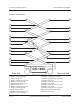
SCISSOR COMPONENTS
48 Place a 4 x 4 x 32 inch (10 x 10 x 81 cm) long
block across both sides of the chassis under
the number 1 center pivot pin (index #12).
49 Attach the strap from the crane to the number 1
inner arm (index #13) at the non-steer end.
Raise the arm slightly and remove the safety
arm. Lower the arm on to the block.
Bodily injury hazard. Keep hands
clear of moving parts when
lowering the arms onto the block.
50 Remove the cables from the number 1 inner
arm (index #13) and lay off to the side.
Component damage hazard.
Cables can be damaged if they
are kinked or pinched.
51 Attach the overhead crane to the number 1
outer arm (index #23). Do not lift it.
52 Remove the pin retaining fasteners from the
number 1 center pivot pin (index #1) at the
ground controls side.
53 Remove the external snap ring. Use a slide
hammer to remove the pin.
54 Repeat steps 52 and 53 for the battery pack
side.
Bodily injury hazard. The number 1
outer arm (index #23) may become
unbalanced and fall if not properly
supported when the pins are
removed.
55 Slide the arm to the non-steer end and remove
the number 1 outer arm (index #23) from the
machine.
Note the position of the wear pads
before the arm is removed so
when the scissor is assembled
they will be in the correct position.
56 Attach the overhead crane to the number 1 inner
arm (index #13). Do not lift it.
57 Remove the pin retaining fasteners from the
number 1 pivot pin (index #14) at the ground
controls side. Use a slide hammer to remove
the pin.
58 Repeat step 57 for the battery pack side.
Remove the number 1 inner arm (index #13)
from the machine.
Bodily injury hazard. The number
1 inner arm (index #13) may
become unbalanced and fall if not
properly supported when the pins
are removed.