
Service manual


Part No. 39528 Genie GS-1530 & Genie GS-1930 5 - 13
Service Manual - First Edition
Section 5 - Troubleshooting Flow Charts
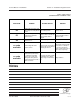
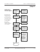
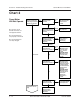
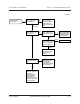
CHART 2
Continued from the
previous page.
Activate lift function and
check voltage on the
output side of PR1.
less than 24V
24V or
more
0V
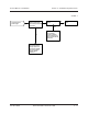
Check continuity on the
brn ground wire on the
coil of K1 to the ground
point on the chassis.
Check voltage on the
output side of the 275A
fuse.
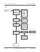
Activate lift function and
check voltage on the
input side of K1.
Activate lift function and
check voltage on the
white wire on the coil of
K1.
24V
no
continuity
continuity
Repair or replace K1.
0V
Repair open in wht wire
(A8-motor) from ECM to
K1 OR replace ECM OR
conult Genie Industries
Service Department.
Repair open in brn
ground wire from K1 to
the ground point on
chassis.
0V
24V
Replace 275A fuse OR
replace positive cable
from 275A fuse to
battery switch OR
consult Genie Industries
Service Department.
Replace positive battery
cables from output side
of 275A fuse to
Anderson plug (AP1)
OR replace positive
battery cables from
Anderson plug to K1 OR
Consult Genie Industries
Service Department.
Replace positive cable
from PR1 to Curtis
controller OR replace
positive cable from
curtis controller to pump
motor.
24V or
more