Genie Executive pBTX 915 User Guide C O M P U T E R S . N E T W O R K S .
Viglen EMC and the ‘CE’ mark CE Marking As we begin the 21st century, European standards are being harmonised across borders. If products comply with the same standards in all European countries, product exporting and importing is made simple - paving our way to a common market. If you buy a product with a 'CE' mark on it (shown below), on the box, in the manual, or on the guarantee - it complies with the currently enforced directive(s).
Copyrights and Trademarks Please note: The material in this manual is subject to change without notice. Trademarks Microsoft, Windows, Windows NT, Windows 95,Windows 98, Windows ME, Windows 2000 Pro, Windows XP Pro and MS-DOS are registered trademarks of Microsoft Corporation. IBM PC, XT, AT and PS/2 are trademarks of International Business Machines Corporation. Pentium® and Pentium® Pro are registered trademarks of Intel® Corporation. All other trademarks are acknowledged.
Contents 1. Overview 5 2. System Introduction 6 Viglen Genie Executive pBTX Front Panel Viglen Genie Executive pBTX Rear Panel Viglen Genie Executive pBTX Internal Components Desktop and Tower Configurations 3.
Advanced Menu USB Configuration CPU Configuration Chipset Onboard Devices Configuration PCIPnP Power Menu AMP Configuration Hardware Monitor Boot Menu Boot Settings Configuration Security Exit Menu 6. Troubleshooting What to do if the system doesn’t work 44 44 45 46 47 48 49 50 51 52 53 54 55 57 57 7. Glossary 60 8. Notes 65 9. Suggestions 69 Viglen Genie Executive pBTX 915 User Guide V1.
1. Overview This manual describes the Viglen Genie Executive 915 pBTX system. The motherboard is the most important part of your computer; it contains all of the CPU, memory and graphics circuitry that makes the Genie Executive pBTX work. Checklist Please check that the following items have been included with your product. If anything listed here is damaged or missing, contact Viglen immediately.
2. System Introduction This chapter gives a general description of the Viglen Genie Executive 915 pBTX system. It includes introduction on the front and rear panel features, and the internal features. The Genie Executive 915 pBTX is a book-size system that delivers power and performance in a light and compact package. This portable heavyweight is powered by a Viglen motherboard that supports Intel® Celeron® D/Pentium® 4 processors in the LGA775 package, 800 MHz front side bus, and up to 2GB system memory.
Viglen Genie Executive pBTX Rear Panel The system rear panel includes the power socket and several I/O ports that allow convenient connection of devices. Figure 2: Rear Panel 1. Cover screws. These screws secure the system cover. 2. Expansion slot. You can insert a PCI expansion board into this slot to add memory and graphics capabilities to the system. 3. Parallel port. This 25-pin port connects a parallel printer, a scanner, or other devices. 4. PS/2 mouse port (Green). This port is for a PS/2 mouse. 5.
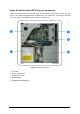
Viglen Genie Executive pBTX Internal Components Figure 3 below shows the internal view of the system when you remove the top cover. The installed components are labelled for your reference. Proceed to Chapter 3 for instructions on installing other system components. Figure 3: Internal Components 1. 2. 3. 4. 5. PCI riser Power supply unit Chassis fan cage Motherboard Storage drive assembly Viglen Genie Executive pBTX 915 User Guide V1.
Desktop and Tower Configurations The Viglen Genie Executive 915 pBTX system is ergonomically designed to save space and complement your desktop. You may use the foot stands provided to place the system vertically in a tower configuration on a flat and stable surface. Please see below for the tower configuration configurations Figure 4: Tower Configuration using the feet provided Viglen Genie Executive pBTX 915 User Guide V1.
3. Basic Installation This chapter provides step by step instructions on how to install components in the system. Basic Components to Install 1. 2. 3. 4. 5. 6. Central processing unit (CPU) CPU heatsink DDR Dual Inline Memory Module Expansion card Hard disk drive Slim type optical drive Tools Required: Philips (cross) screw driver.
• Motherboard Battery: CAUTION - There is a danger of explosion if the onboard battery is installed upside down, which will reverse its polarities. On the Genie Executive pBTX, the positive side should be facing up. This battery must be replaced only with the same or an equivalent type recommended by the manufacturer. Dispose of used batteries according to the manufacturer's instructions.
• Put the motherboard and peripherals back into their antistatic bags when not in use. • For grounding purposes, make sure your computer chassis provides excellent conductivity between the power supply, the case, the mounting fasteners and the motherboard. Operating Precautions Care must be taken to assure that the chassis cover is in place when the Viglen Genie Executive pBTX is operating to assure proper cooling.
Removing the Top Cover and Front Bezel To remove the cover: 1. Locate the two screws that secure the foot stands to the cover and the chassis. Figure 6: Removing the foot stand screws 2. Remove the screws using a Phillips screw driver. Keep the screws for later use and set the foot stands aside. 3. On the rear panel, locate the two screws that secure the cover to the chassis. Figure 7: Removing the Top Cover Screws 4. Remove the cover screws using a Phillips screw driver. Keep the screws for later use.
Figure 9: Remove the Front Panel 7. Lift the front bezel hooks outward until they disengage from the chassis. 8. Carefully remove the front cover, and then set it aside. CAUTION: Remove the SATA cable from the hard disk drive before you open the front bezel, otherwise the hard disk drives SATA connector may be easily damaged. Opening the Storage Drive Assembly Opening the storage drive assembly gives you more space when installing the CPU and the CPU heatsink. To open the storage drive assembly: 1.
Figure 11: Storage Assembly in maximum Orientation CAUTION: When fully open, the storage drive assembly remains slightly tilted. Do not push down further to prevent damage to the system. Installing the System Memory The system motherboard comes with two Double Data Rate (DDR) Dual Inline Memory Module(s) (DIMM) sockets that support up to 2GB system memory using unbuffered ECC and non-ECC PC32--/2700 DIMMS.
• • • Always install DIMMs with the same CAS latency. For optimum compatibility, we recommend that you obtain memory modules from Viglen Ltd to guarantee consistency in product. Due to chipset resource allocation, the system may detect less than 2GB system memory when you installed two 1GB DDR memory. This motherboard does not support memory modules made up of 128Mb chips or double-sided x16 memory modules. Installing and Removing Memory Installing Memory 1.
Figure 13: Removing DIMMs Uninstalling the CPU Heatsink You need to remove the proprietary CPU heatsink assembly from the motherboard before you can install a CPU. To uninstall the CPU heatsink: 1. Open the storage drive assembly. Refer to the previous section for details. 2. Using a Philips screw driver, remove the four screws that secure the CPU heatsink to the motherboard. Figure 14: Unscrewing the Heatsink 3. Lift the CPU heatsink, and then set it aside.
Installing the CPU To install a CPU: 1. Locate the CPU socket on the motherboard. Figure 15: CPU Socket 775 Location Note: Before installing the CPU, make sure that the cam box is facing towards you and the load lever is on your left. 2. Press the load lever with your thumb (a), then move it to the left (b) until it is released from the retention tab. Figure 16: Pressing the Load Lever CAUTION: To prevent damage to the socket pins, do not remove the PnP cap unless you are installing a CPU. 3.
4. Lift the load plate with your thumb and forefinger to a 100º angle (A), then push the PnP cap from the load plate window to remove (B). Figure 18: Lifting the Load Plate 5. Position the CPU over the socket, making sure that the gold triangle is on the bottom-left corner of the socket. The socket alignment key should fit into the CPU notch. Figure19: Positioning the CPU 6. Close the load plate (A), then push the load lever (B) until it snaps into the retention tab.
CAUTION: The CPU fits in only one correct orientation. DO NOT force the CPU into the socket to prevent bending the connectors on the socket and damaging the CPU! Notes on Intel® Hyper-Threading Technology • This motherboard supports Intel® Pentium® 4 CPUs in the 775-land package with Hyper-Threading Technology. • Hyper-Threading Technology is supported under Windows® XP and Linux 2.4.x (kernel) and later versions only. Under Linux, use the Hyper-Threading compiler to compile the code.
Figure 21: Reinstalling the Heatsink 3. Close the storage drive assembly. CAUTION: Please make sure that the CPU fan connectors are plugged in. Hardware monitoring errors may occur if you fail to plug this connector. Expansion Slots In the future, you may need to install an expansion card. The following sub-sections describe the slots and the expansion cards that they support. CAUTION: Make sure to unplug the power cord before adding or removing expansion cards.
Figure 22: Lifting the Riser Assembly 4. Place the PCI riser on a flat surface Figure 23: PCI Riser Assembly 5. Remove the screw securing the card slot cover (see Figure 24). Keep the screw for later use. 6. Align the PCI card connector with the slot and press firmly until the card is completely seated on the slot. Viglen Genie Executive pBTX 915 User Guide V1.
Figure 24: Installing the PCI Card 7. Secure the card to the PCI riser assembly with the screw you removed earlier. Figure 25: Securing the PCI card to the Riser Assembly 8. Reinstall the PCI riser to the system chassis. Figure 26: Reinstalling the PCI riser Viglen Genie Executive pBTX 915 User Guide V1.
CAUTION: Take extra care when removing and reinstalling the PCI riser assembly to prevent sharp edges from causing injury. 9. Please make sure the PCI riser side tabs completely fit the chassis. Figure 27: PCI Riser Tabs Configuring an Expansion Card After installing the expansion card, configure it by adjusting the software settings. 1. Turn on the system and change the necessary BIOS settings, if any. 2. Assign an IRQ to the card. Refer to the tables below. 3.
Table 2: IRQ Assignment for this Motherboard A B C PCI slot 1 PCI slot 2 PCI Express x16 slot shared PCI Express x1 slot shared Onboard USB controller 1 Onboard USB controller 2 Onboard USB controller 3 shared Onboard USB controller 4 shared Onboard USB 2.
Figure 29: Installing the Slim Line Optical Drive 3. Push the lock tab to the left to secure the optical drive in place. Figure 30: Pushing the Lock Tab 4. Connect a power cable from the power supply to the power connector at the back of the optical drive. Figure 31: Connecting the Cables to the Optical Drive 5. Connect the black interface of the IDE ribbon cable to the IDE interface at the back of the optical drive, matching the red stripe on the cable with Pin 1 on the IDE interface. 6.
Installing a Hard Disk Drive The Viglen Genie Executive pBTX supports one Serial ATA hard disk drive. To install a Serial ATA hard disk drive, follow the below procedure: 1. Slightly lift the storage drive assembly. 2. With the hard disk drive label side up, carefully insert the drive into the 3.5” bay. Figure 32: Inserting the Hard Disk Drive 3. Push the drive into the bay until its screw holes align with the holes on the bay. Figure 33: Aligning the Hard Disk Drive Holes 4.
6. Connect a 15-pin Serial ATA power plug from the power supply unit to the power connector at the back of the drive. Or connect a 4-pin (female) power plug from the power supply unit to the 4-pin (male) power connector at the back of the drive. CAUTION: If the Serial ATA hard disk drive has both 4-pin and 15-pin connectors at the back, use either the 15-pin Serial ATA power adapter plug or the legacy 4-pin power connector.
Figure 37: Reinstalling the system screws Installing the Foot Stand You may prefer to position the system vertically to save space. You must reinstall the foot stands to place the system upright to prevent accidental damage. To reinstall the foot stands, please follow the below procedure: 1. Fit the foot stands on the chassis cover. Figure 38: Reattaching the Foot Stands 2. Align the foot stand screw holes with the cover holes. Figure 39: Aligning the Screw Holes 3.
4. Motherboard Information A Motherboard comes already installed in the Viglen Genie Executive 915 pBTX system. This section provides technical information about the motherboard for future upgrades or system reconfiguration. Motherboard Layout Figure 40: Viglen Genie Executive pBTX Motherboard Layout Motherboard Jumpers Clear RTC RAM (CLRTC) This jumper allows you to clear the Real Time Clock (RTC) RAM in CMOS.
Figure 41: Clear RTC RAM Note: Except when clearing the RTC RAM, never remove the cap on CLRTC jumper default position. Removing the cap will cause system boot failure. USB Device Wake-Up (3-pin USBPW12) Set these jumpers to +5V to wake up the computer from S1 sleep mode (CPU stopped, DRAM refreshed, system running in low power mode) using the connected USB devices. Set to +5VSB to wake up from S3 and S4 sleep modes (no power to CPU, DRAM in slow refresh, power supply in reduced power mode).
Figure 43: Keyboard Power Setting Connectors Floppy Disk Drive Connector This connector is for the provided floppy disk drive (FDD) signal cable. Insert one end of the cable to this connector, and then connect the other end to the signal connector at the back of the floppy disk drive. Figure 44: Floppy Disk Drive Connector Primary IDE Connector (40-1 pin PRI_IDE) This connector is for an Ultra DMA 100/66 signal cable.
Figure 45: IDE Connector Serial ATA Connector (7-pin SATA) This connector is for the Serial ATA signal cable for a Serial ATA hard disk drive. Figure 46: SATA Connectors CPU Fan Connectors (3-pin CPU_FAN1, 3-pin CPU_FAN2) The fan connectors support cooling fans of 350 mA~740 mA (8.88 W max.) or a total of 1 A~2.22 A (26.64 W max.) at +12V. Connect the fan cables to the fan connectors on the motherboard, making sure that the black wire of each cable matches the ground pin of the connector.
Figure 47: CPU Fan Connectors ATX Power Connectors (20-pin ATXPWR, 4-pin ATX12V) These connectors are for ATX power supply plugs. The plugs from the power supply are designed to fit these connectors in only one orientation. Find the proper orientation and push down firmly until the connectors completely fit. Figure 48: ATX Power Connector Important Notes on the motherboard power requirements: • • • • Do not forget to connect the 4-pin ATX +12V power plug; otherwise, the system will not boot up.
These connectors are for the USB device module. Figure 49: USB 2.0 Connectors CAUTION: Never connect an IEEE-1394 cable to the USB connector. Doing so will damage the motherboard. Optical Drive Audio Connector (4-pin CD) This connector is for the 4-pin audio cable that connects to the audio connector at the back of the optical drive. Figure 50: Internal Audio connector Note: Use this connector only if the optical drive has an analog audio output.
Figure 51: Front Panel Audio Connector System Panel Connector (12-1 pin CONTROL) This connector supports several chassis-mounted functions. Figure 52: System Panel Connector Hard Disk Drive Activity LED (2-pin HDD_LED) This 2-pin connector is for the hard disk drive activity LED. Connect the hard disk drive activity LED cable to this connector. The IDE LED lights up or flashes when data is read from or written to the hard disk drive.
Power LED (2-pin POWER_LED) This 2-pin connector is for the power LED. The LED lights up when system power is on. Suspend LED (2-pin SUSPEND_LED) This 2-pin connector is for the suspend LED. The LED lights up when the system is in suspend mode. Viglen Genie Executive pBTX 915 User Guide V1.
5. System BIOS BIOS Setup Program This motherboard supports a programmable firmware chip that you can update using the Viglen supplied utility. Use the BIOS setup program when you are installing a motherboard, reconfiguring you system, or prompted to “Run Setup”. This section explains how to configure you system using this utility. Even if you are not prompted to use the Setup Program, you can change the configuration of you computer in the future.
BIOS Menu Screen Figure 53: BIOS Menu Screen Menu Bar The menu bar on top of the screen has the following main items: Table 3: Menu Bar Main For changing the basic system configuration Advanced For changing the advanced system settings Power For changing the advanced power management (APM) configuration Boot For changing the system boot configuration Exit For selecting the exit options and loading default settings To select an item on the menu bar, press the right or left arrow key on the keyboard until
Main Menu When you enter the BIOS Setup program, the Main menu screen appears, giving you an overview of the basic system information. Figure 54: BIOS Main Menu Screen System Time [xx:xx:xx] Allows you to set the system time. System Date [Day xx/xx/xxxx] Allows you to set the system date. Legacy Diskette A [1.44M, 3.5 in.] Sets the type of floppy drive installed. Configuration options: [Disabled] [1.44M, 3.5 in.] Viglen Genie Executive pBTX 915 User Guide V1.
Primary/Third/Fourth IDE Master/Slave While entering Setup, the BIOS automatically detects the presence of IDE devices. There is a separate sub-menu for each IDE device. Select a device item then press to display the IDE device information. Figure 55: BIOS Primary IDE Master Screen The BIOS automatically detects the values opposite the dimmed items (Device, Vendor, Size, LBA Mode, Block Mode, PIO Mode, Async DMA, Ultra DMA, and SMART monitoring). These values are not user-configurable.
SMART Monitoring [Auto] Sets the Smart Monitoring, Analysis, and Reporting Technology. Configuration options: [Auto] [Disabled] [Enabled] 32Bit Data Transfer [Disabled] Enables or disables 32-bit data transfer. Configuration options: [Disabled] [Enabled] IDE Configuration The items in this menu allow you to set or change the configurations for the IDE devices installed in the system. Select an item then press if you want to configure the item.
IDE Detect Time Out (Sec) [35] Select the time out value for detecting ATA/ATAPI device(s). Configuration options: [0] [5] [10] [15]...[35] System information This menu gives you an overview of the general system specifications. The BIOS automatically detects the items in this menu. Figure 57: System information Screen AMI BIOS Displays the auto-detected BIOS information. Processor Displays the auto-detected CPU specification. Memory Size/Mode/Channel Displays the auto-detected system memory information.
Advanced Menu The Advanced menu items allow you to change the settings for the CPU and other system devices. CAUTION: Take caution when changing the settings of the Advanced Menu items. Incorrect field values can cause the system to malfunction. Figure 58: Advanced Menu Screen. USB Configuration The items in this menu allows you to change the USB-related features. Select an item then press to display the configuration options.
Legacy USB Support [Auto] Enables support for legacy USB. AUTO option disables legacy support if no USB devices are connected. Configuration options: [Disabled] [Enabled] [Auto] USB 2.0 Controller [Enabled] Allows you to enable or disable the USB 2.0 controller. Configuration options: [Disabled] [Enabled] USB 2.0 Controller Mode [HiSpeed] Configures the USB 2.0 controller in HiSpeed (480Mbps) or FullSpeed (12Mbps).
Intel(R) SpeedStep(tm) Tech. [Automatic] Enable/Disable Intel Speed Step Support in BIOS. Configuration options: [Automatic] [Disabled] Chipset The Chipset menu allows you to change the advanced chipset settings. Select an item then press to display the sub-menu. Figure 61: Chipset Settings Screen Configure DRAM Timing by SPD [Enabled] When this item is enabled, the DRAM timing parameters are set according to the DRAM SPD (Serial Presence Detect).
DRAM Write Recovery Time [4 Clocks] Sets the DRAM Burst Length. Configuration options: [2 Clocks]...[8 Clocks] Graphic Adapter Priority [Internal VGA] Select which graphics controller to use as the primary boot device. Configuration options: [Internal VGA] [PCI/Int-VGA] Internal Graphics Mode Selec [Enabled, 8MB] Select the amount of system memory reallocated by the internal graphics device.
Parallel Port Address [378] Allows you to select the Parallel Port base addresses. Configuration options: [Disabled] [378] [278] [3BC] Parallel Port Mode [ECP] Allows you to select the Parallel Port mode. Configuration options: [Normal] [Bidirectional] [EPP] [ECP] ECP Mode DMA Channel [DMA3] Appears only when the Parallel Port Mode is set to [ECP]. This item allows you to set the Parallel Port ECP DMA.
Power Menu The Power menu items allow you to change the settings for the Advanced Power Management (APM) and Advanced Configuration and Power Interface (ACPI). Select an item then press to display the configuration options. Figure 64: Power Menu Screen Suspend Mode [Auto] Allows you to select the Advanced Configuration and Power Interface (ACPI) state to be used for system suspend.
AMP Configuration Figure 65: AMP Configuration Screen Power button Mode [On/Off] Selects going into On/Off or suspend when power button is pressed. Configuration options: [On/Off] [Suspend] Restore on AC Power Loss [Power Off] When set to Power Off, the system goes into off state after an AC power loss. When set to Power On, the system goes on after an AC power loss. When set to Last State, the system goes into either off or on state, whatever the system state was before the AC power loss.
Power On By PCIE Devices [Disabled] Disable/Enable PCIE to generate a wake event. Configuration options: [Disabled] [Enabled] Power On By PS/2 Keyboard [Disabled] Allows you to use specific keys on the keyboard to turn on the system. This feature requires an ATX power supply that provides at least 1A on the +5VSB lead. Configuration options: [Disabled] [Enabled] Keyboard Wakeup Password This item appears only when the Power On By PS/2 Keyboard is set to Enabled.
CPU Q-Fan Control [Enabled] Allows you to enable or disable the ASUS Q-Fan feature that smartly adjusts the fan speeds for more efficient system operation. When this field is set to [Enabled], the CPU Fan Ratio item appears to allow selection of the appropriate fan speed ratio. Configuration options: [Disabled] [Enabled] CPU Fan2 Speed [xxxxRPM], [N/A], or [Ignored] The onboard hardware monitor automatically detects and displays the CPU fan speed in rotations per minute (RPM).
1st ~ xxth Boot Device [1st Floppy Drive] These items specify the boot device priority sequence from the available devices. The number of device items that appears on the screen depends on the number of devices installed in the system. Configuration options: [xxxxx Drive] [Disabled] Boot settings Configuration Figure 69: Boot Settings Configuration Screen Quick Boot [Enabled] Allows BIOS to skip certain tests while booting. This will decrease the time needed to boot the system.
Security The Security menu items allow you to change the system security settings. Select an item then press to display the configuration options. Figure 70: Security Screen Change Supervisor Password Select this item to set or change the supervisor password. The Supervisor Password item on top of the screen shows the default Not Installed. After you set a password, this item shows Installed. To set a Supervisor Password: 1. Select the Change Supervisor Password item and press . 2.
Figure 71: Change Supervisor Password Screen Password Check [Setup] When set to [Setup], BIOS checks for user password when accessing the Setup utility. When set to [Always], BIOS checks for user password both when accessing Setup and booting the system. Configuration options: [Setup] [Always] Boot Sector Virus Protection [Disabled] Allows you to enable or disable the boot sector virus protection.
Exit & Save Changes Once you are finished making your selections, choose this option from the Exit menu to ensure the values you selected are saved to the CMOS RAM. An onboard backup battery sustains the CMOS RAM so it stays on even when the PC is turned off. When you select this option, a confirmation window appears. Select Yes to save changes and exit.
6. Troubleshooting What to do if the system doesn’t work This section describes basic problems and the remedies that can be used if the system does not seem to work correctly. Most problems can be sorted out very quickly once the root cause is established. Before seeking assistance, have a look at these common problems and their possible solutions. Try, wherever possible to isolate the problem by trying out a replacement device (i.e. mouse, keyboard etc.) if one is at hand.
Problem Action Main system unit is OK, but no display or incorrect display on monitor Check the power light on the monitor. If this is not lit, then check that the monitor power ON/OFF switch is in the ON position. Check that the AC power lead at the rear of the monitor is plugged firmly into the monitor and the power outlet at the rear of the main system unit.
Problem Action No input from the keyboard Check that the keyboard plug is firmly inserted into the socket labelled ‘keyboard’ at the rear of the main system unit. If the ‘Caps Lock’ LED lights up when pressed, there is an electrical connection. Problem Action The mouse is not being recognised. The mouse is not plugged in correctly. Solution: Check mouse plug - make sure the plug is inserted in the correct port. The plug may become loose after prolonged use.
7. Glossary This section gives a brief description of the most commonly used computer terms. A Ampere, This is a term of measurement for electric Current. AC Alternating Current used to describe the mains voltage. Ampere This is a term of measurement of electric current. Analog Pertaining to data in the form of continuously variable quantities. Contrasts with Digital. ANSI American National Standards Institute. ASCHS American Standard Coded for Information Interchange.
BSI British Standards Institute. Bps Bits per second. Buffer An area of temporary storage. Bus One or more conductors used for transmitting signals. Byte A unit of data made up of eight Bits. C / C++ A programming language. Cache A small area of high-speed memory. Cathode Ray Tube (CRT) Normally referred to as a monitor or VDU. Character A symbol on the screen or same as a Byte. CMOS Complementary Metal Oxide Semiconductor. A logic circuit family that uses very little power.
DOS or MS-DOS® Disk Operating System or Microsoft Disk Operating System. This is a low-level program that instructs the computer on basic file handling.# DRAM Dynamic RAM. A type of RAM that requires a periodic refresh to maintain data. DVD Digital Versatile Disk EMC Electromagnetic Compatibility EMI Electromagnetic Interference. EPROM Erasable Programmable Read-Only Memory. ESDI Enhanced Small Device Interface, which specifies a fast hard disk interface.
K Symbol used to represent Kilobyte which is 1024 bytes. KB Abbreviation for Kilobyte, i.e. 1024 bytes. Kb Abbreviation for Kilo bit, i.e. 1024 bits. Keylock A locking device which can deactivate a keyboard. KHz KiloHertz. 1000 Hertz. LIM Lotus/Intel/ Microsoft Expanded Memory Manager specification. LED Light Emitting Diode. These are normally used as the lights on a computers front panel. LPT1, LPT2, LPT3 Names given to the printer ports by DOS. M Prefix mega. Equivalent to 1024K.
Software Another name for a computer program. SRAM Static RAM. Synchronous Transmission of data between devices which are maintaining the same frequency relationship. Contrasts with asynchronous. TPI Tracks Per Inch. TTL Transistor Transistor Logic. TUV Technischer Uberwachungs-Verein. Organisation which tests and certifies electronic equipment. UL Underwriter Laboratories. American Organisation specifying standards for safety of electronic equipment. USB Universal Serial Bus V Volt.
8. Notes Viglen Genie Executive pBTX 915 User Guide V1.
Viglen Genie Executive pBTX 915 User Guide V1.
Viglen Genie Executive pBTX 915 User Guide V1.
Viglen Genie Executive pBTX 915 User Guide V1.
9. Suggestions Viglen is interested in continuing to improve the quality and information provided in their manuals. Viglen has listed some questions that you may like to answer and return to Viglen. This will help Viglen help to keep and improve the standard of their manuals. 1. Is the information provided in this and other manuals clear enough? 2. What could be added to the manual to improve it? 3. Does the manual go into enough detail? 4. Would you like an on-line version of this manual? 5.
6. Are there any technological improvements that could be made to the system? 1. Other points you would like to mention? Please return this slip to: Product Development Dept. Vigen Head Quarters 7 Handley Page Way Old Parkbury Lane Colney Street St Albans Hertfordshire AL2 2DQ Viglen Genie Executive pBTX 915 User Guide V1.