Motherboard H87I-PLUS
E8210 First Edition April 2013 Copyright © 2013 ASUSTeK COMPUTER INC. All Rights Reserved. No part of this manual, including the products and software described in it, may be reproduced, transmitted, transcribed, stored in a retrieval system, or translated into any language in any form or by any means, except documentation kept by the purchaser for backup purposes, without the express written permission of ASUSTeK COMPUTER INC. (“ASUS”).
Contents Safety information....................................................................................................... iv About this guide.......................................................................................................... iv Package contents........................................................................................................ vi H87I-PLUS specifications summary..........................................................................
Safety information Electrical safety • To prevent electrical shock hazard, disconnect the power cable from the electrical outlet before relocating the system. • When adding or removing devices to or from the system, ensure that the power cables for the devices are unplugged before the signal cables are connected. If possible, disconnect all power cables from the existing system before you add a device.
Where to find more information Refer to the following sources for additional information and for product and software updates. 1. ASUS websites The ASUS website provides updated information on ASUS hardware and software products. Refer to the ASUS contact information. 2. Optional documentation Your product package may include optional documentation, such as warranty flyers, that may have been added by your dealer. These documents are not part of the standard package.
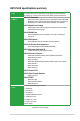
Package contents Check your motherboard package for the following items. Motherboard ASUS H87I-PLUS motherboard Cables 2 x Serial ATA 6.0 Gb/s cables Accessories 1 x I/O Shield Application DVD Support DVD Documentation User Guide If any of the above items is damaged or missing, contact your retailer. H87I-PLUS specifications summary CPU LGA1150 socket for Intel® 4th Generation CoreTM i7/ i5 / i3, Pentium®, Celeron® Processors Supports 22nm CPU Supports Intel® Turbo Boost Technology 2.
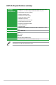
H87I-PLUS specifications summary USB 6 x USB 3.0/2.0 ports (4 ports at back panel, [blue], 2 ports at mid-board) 8 x USB 2.0/1.
H87I-PLUS specifications summary Internal I/O connectors/ buttons/switches 1 x USB 3.0/2.0 connector supports additional 2 USB 3.0/2.0 ports (19-pin) 2 x USB 2.0/1.1 connectors support additional 4 USB 2.0/1.1 ports 6 x SATA 6.
Product introduction 1.1 Before you proceed 1 Take note of the following precautions before you install motherboard components or change any motherboard settings. 1.2 • Unplug the power cord from the wall socket before touching any component. • Before handling components, use a grounded wrist strap or touch a safely grounded object or a metal object, such as the power supply case, to avoid damaging them due to static electricity.
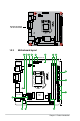
H87I-PLUS Place this side towards the rear of the chassis 1.2.3 Motherboard layout 1 2 3 4 5 6 7 8 EATXPWR 17cm(6.7in) CLRTC KBMS_USB56 CHA_FAN CPU_FAN DIGI +VRM SPDIFO _HDMI ATX12V Super I/O USB1112 AUDIO USB78 AAFP 1-2 17cm(6.
1.2.4 Layout contents Connectors/Jumpers/Slots/LED Page 1. Onboard LED (SB_PWR) 1-18 2. USB 3.0 connector (20-1 pin USB_1314) 1-16 3. ATX power connectors (24-pin EATXPWR, 4-pin ATX12V) 1-15 4. Intel® LGA1150 CPU socket 1-3 5. CPU and chassis fan connectors (4-pin CPU_FAN, 4-pin CHA_FAN) 1-14 6. Clear RTC RAM (3-pin CLRTC) ) 1-10 7. DDR3 DIMM slots 1-6 8. Speaker connector (4-pin SPEAKER) 1-15 9. System panel connector (10-1 pin F_PANEL) 1-17 10. Intel® H87 Serial ATA 6.
1.3.
1.3.2 CPU heatsink and fan assembly installation Apply the Thermal Interface Material to the CPU heatsink and CPU before you install the heatsink and fan if necessary.
To uninstall the CPU heatsink and fan assembly 2 1 A B B A 1.4 System memory 1.4.1 Overview DIMM_A1 DIMM_B1 This motherboard comes with two Double Data Rate 3 (DDR3) Dual Inline Memory Module (DIMM) sockets. A DDR3 module has the same physical dimensions as a DDR2 DIMM but is notched differently to prevent installation on a DDR2 DIMM socket. DDR3 modules are developed for better performance with less power consumption.
• You may install varying memory sizes in Channel A and Channel B. The system maps the total size of the lower-sized channel for the dual-channel configuration. Any excess memory from the higher-sized channel is then mapped for single-channel operation. • Due to Intel® chipset limitation, DDR3 1600MHz and higher memory modules on XMP mode will run at the maximum transfer rate of DDR3 1600MHz. • Always install DIMMs with the same CAS latency.
2 DIMM notch 1 Unlocked retaining clip DIMM slot key A DIMM is keyed with a notch so that it fits in only one direction. DO NOT force a DIMM into a socket in the wrong direction to avoid damaging the DIMM. 3. 3 Firmly insert the DIMM into the socket until the retaining clips snap back in place and the DIMM is properly seated. Locked Retaining Clip 1.4.4 Removing a DIMM To remove a DIMM: 1. Simultaneously press the retaining clips outward to unlock the DIMM.
1.5.1 Installing an expansion card To install an expansion card: 1. Before installing the expansion card, read the documentation that came with it and make the necessary hardware settings for the card. 2. Remove the system unit cover (if your motherboard is already installed in a chassis). 3. Remove the bracket opposite the slot that you intend to use. Keep the screw for later use. 4. Align the card connector with the slot and press firmly until the card is completely seated on the slot. 5.
1.6 Jumpers Clear RTC RAM (3-pin CLRTC) This jumper allows you to clear the Real Time Clock (RTC) RAM in CMOS. You can clear the CMOS memory of date, time, and system setup parameters by erasing the CMOS RTC RAM data. The onboard button cell battery powers the RAM data in CMOS, which include system setup information such as system passwords. CLRTC H87I-PLUS 1 2 2 3 Normal (Default) Clear RTC H87I-PLUS Clear RTC RAM To erase the RTC RAM: 1. Turn OFF the computer and unplug the power cord. 2.
1.7 Connectors 1.7.1 Rear panel connectors 1 2 3 13 12 11 5 6 4 10 9 7 8 1. PS/2 Keyboard/Mouse combo port. This port is for a PS/2 keyboard/mouse. 2. Optical S/PDIF Out port. This port connects an external audio output device via an optical S/PDIF cable 3. Video Graphics Adapter (VGA) port. This 15-pin port is for a VGA monitor or other VGA-compatible devices. 4. LAN (RJ-45) port. This port allows Gigabit connection to a Local Area Network (LAN) through a network hub.
Audio 2, 4, 6, or 8-channel configuration Port Light Blue (Rear panel) Lime (Rear panel) Pink (Rear panel) Lime (Front panel) Headset 2-channel Line In Line Out Mic In - 4-channel Rear Speaker Out Front Speaker Out Mic In - 6-channel Rear Speaker Out Front Speaker Out Bass/Center - 8-channel Rear Speaker Out Front Speaker Out Bass/Center Side Speaker Out 8. USB 2.0 ports 1 and 2. These two 4-pin Universal Serial Bus (USB) ports are for USB 2.0/1.1 devices. 9. USB 3.0 ports 1 and 2.
1.7.2 1. Internal connectors Front panel audio connector (10-1 pin AAFP) NC AGND NC NC SENSE2_RETUR AGND NC SENSE1_RETUR This connector is for a chassis-mounted front panel audio I/O module that supports either HD Audio or legacy AC`97 audio standard. Connect one end of the front panel audio I/O module cable to this connector.
3. CPU and chassis fan connectors (4-pin CPU_FAN, 4-pin CHA_FAN) Connect the fan cables to the fan connectors on the motherboard, ensuring that the black wire of each cable matches the ground pin of the connector. CPU_FAN CPU FAN PWM CPU FAN IN CPU FAN PWR GND CHA FAN PWM CHA FAN IN CHA FAN PWR GND H87I-PLUS CHA_FAN H87I-PLUS Fan connectors Do not forget to connect the fan cables to the fan connectors. Insufficient air flow inside the system may damage the motherboard components.
5. ATX power connectors (24-pin EATXPWR, 4-pin ATX12V) These connectors are for ATX power supply plugs. The power supply plugs are designed to fit these connectors in only one orientation. Find the proper orientation and push down firmly until the connectors completely fit.
7. USB 2.0 connectors (10-1 pin USB78, USB1112) These connectors are for USB 2.0 ports. Connect the USB module cable to any of these connectors, then install the module to a slot opening at the back of the system chassis. These USB connectors comply with USB 2.0 specifications and supports up to 480Mbps connection speed. USB78 PIN 1 USB+5V USB_P8USB_P8+ GND USB+5V USB_P7USB_P7+ GND NC USB+5V USB_P11USB_P11+ GND NC PIN 1 USB+5V USB_P12USB_P12+ GND H87I-PL US USB1112 H87I-PLUS USB2.
9. System panel connector (20-8 pin PANEL) This connector supports several chassis-mounted functions. PIN 1 RESET (NC) HWRST# Ground HDD_LEDHDD_LED+ GND PWR PWR_LEDPWR_LED+ +HD_LED PWR_LED PWR_BTN H87I-PL US F_PANEL H87I-PLUS System panel connector • System power LED (2-pin PWR_LED) This 2-pin connector is for the system power LED. Connect the chassis power LED cable to this connector. The system power LED lights up when you turn on the system power, and blinks when the system is in sleep mode.
1.8 1. Onboard LEDs Standby Power LED H87I-PLUS The motherboard comes with a standby power LED that lights up to indicate that the system is ON, in sleep mode, or in soft-off mode. This is a reminder that you should shut down the system and unplug the power cable before removing or plugging in any motherboard component. The illustration below shows the location of the onboard LED.
1.9 1.9.1 Software support Installing an operating system This motherboard supports Windows® 7 (32bit/64bit) and Windows® 8 (32bit/64bit) Operating Systems (OS). Always install the latest OS version and corresponding updates to maximize the features of your hardware. Motherboard settings and hardware options vary. Refer to your OS documentation for detailed information. 1.9.
BIOS information 2.1 Managing and updating your BIOS 2 Save a copy of the original motherboard BIOS file to a USB flash disk in case you need to restore the BIOS in the future. Copy the original motherboard BIOS using the ASUS Update utility. 2.1.1 EZ Update EZ Update is a utility that allows you to automatically update your motherboard’s softwares, drivers and the BIOS version easily.
2.1.2 ASUS EZ Flash 2 The ASUS EZ Flash 2 feature allows you to update the BIOS without using an OS‑based utility. Before you start using this utility, download the latest BIOS file from the ASUS website at www.asus.com. To update the BIOS using EZ Flash 2: 2-2 1. Insert the USB flash disk that contains the latest BIOS file to the USB port. 2. Enter the Advanced Mode of the BIOS setup program. Go to the Tool menu to select ASUS EZ Flash 2 Utility and press to enable it. 3.
2.1.3 ASUS CrashFree BIOS 3 utility The ASUS CrashFree BIOS 3 is an auto recovery tool that allows you to restore the BIOS file when it fails or gets corrupted during the updating process. You can restore a corrupted BIOS file using the motherboard support DVD or a USB flash drive that contains the updated BIOS file. • Before using this utility, rename the BIOS file in the removable device into H87IP.CAP. • The BIOS file in the support DVD may not be the latest version.
Booting the system in DOS environment 1. Insert the USB flash drive with the latest BIOS file and BIOS Updater to the USB port. 2. Boot your computer. When the ASUS Logo appears, press to show the BIOS Boot Device Select Menu. Insert the support DVD into the optical drive and select the optical drive as the boot device. 3. When the Make Disk menu appears, select the FreeDOS command prompt item by pressing the item number. 4.
3. Press to switch between screen fields and use the keys to select the BIOS file and press . BIOS Updater checks the selected BIOS file and prompts you to confirm BIOS update. 4. Select Yes and press . When BIOS update is done, press to exit BIOS Updater. Restart your computer. DO NOT shut down or reset the system while updating the BIOS to prevent system boot failure! • For BIOS Updater version 1.
2.2 BIOS setup program Use the BIOS Setup program to update the BIOS or configure its parameters. The BIOS screens include navigation keys and brief online help to guide you in using the BIOS Setup program. Entering BIOS Setup at startup To enter BIOS Setup at startup: • Press during the Power-On Self Test (POST). If you do not press , POST continues with its routines. Entering BIOS Setup after POST To enter BIOS Setup after POST: • Press ++ simultaneously.
Selects the display language of the BIOS setup program Displays the CPU/motherboard temperature, CPU/5V/3.
Back button Menu items Submenu item Menu bar Configuration fields Pop-up window Scroll bar General help Navigation keys Last modified settings Quick note Menu bar The menu bar on top of the screen has the following main items: My Favorites For saving the frequently-used system settings and configuration Main For changing the basic system configuration Ai Tweaker For changing the overclocking settings Advanced Boot For changing the advanced system settings For displaying the system temperature,
Submenu items A greater than sign (>) before each item on any menu screen means that the item has a submenu. To display the submenu, select the item and press . Pop-up window Select a menu item and press to display a pop-up window with the configuration options for that item. Scroll bar A scroll bar appears on the right side of a menu screen when there are items that do not fit on the screen.
2.3 My Favorites MyFavorites is your personal space where you can easily save and access your favorite BIOS items. Adding items to My Favorites To add frequently-used BIOS items to My Favorites: 1. Use the arrow keys to select an item that you want to add. When using a mouse, hover the pointer to the item. 2. Press on your keyboard or right-click on your mouse to add the item to My Favorites page.
2.4 Main menu 2.4.1 System Language [English] The Main menu screen appears when you enter the Advanced Mode of the BIOS Setup program. The Main menu provides you an overview of the basic system information, and allows you to set the system date, time, language, and security settings. Allows you to choose the BIOS language version from the options. Configuration options: [English] [Español] [Русский] [한국어] 2.4.2 System Date [Day xx/xx/xxxx] Allows you to set the system date. 2.4.
Administrator Password If you have set an administrator password, we recommend that you enter the administrator password for accessing the system. Otherwise, you might be able to see or change only selected fields in the BIOS setup program. To set an administrator password: 1. Select the Administrator Password item and press . 2. From the Create New Password box, key in a password, then press . 3. Confirm the password when prompted. To change an administrator password: 1.
2.5 Ai Tweaker menu The Ai Tweaker menu items allow you to configure overclocking-related items. Be cautious when changing the settings of the Ai Tweaker menu items. Incorrect field values can cause the system to malfunction. The configuration options for this section vary depending on the CPU and DIMM model you installed on the motherboard.
Scroll down to display the following items: Scroll down to display the following items: Target CPU Turbo-Mode Speed : xxxxMHz Displays the target CPU Turbo-Mode speed. Target DRAM Speed : xxxxMHz Displays the target DRAM speed. Target Cache Speed : xxxxMHz Displays the target Cache speed. Target DMI/PCIE Clock : xxxxMHz Displays the target DMI/PCIE clock.
Target CPU Graphics Speed : xxxxMHz Displays the target CPU Graphics speed. 2.5.1 Ai Overclock Tuner [Auto] Allows you to select the CPU overclocking options to achieve the desired CPU internal frequency. Select any of these preset overclocking configuration options: [Auto] Loads the optimal settings for the system. [Manual] Allows you to automatically optimize the CPU ratio and BCLK frequency. [X.M.P.
4-Core Ratio Limit [Auto] This item becomes configurable only when the CPU Core Ratio is set to [Per Core] and allows you to set the 4 Core Ratio Limit. Select [Auto] to apply the CPU default Turbo Ratio setting or manually assign a 4-Core Ratio Limit value that is higher than or equal to the 3Core Ratio Limit. 1-Core/2-Core/3-Core Limit must not be set to [Auto]. 2.5.4 Min CPU Cache Ratio [Auto] Allows you to set the uncore ratio of the processor to its possible minimum value.
2.5.11 DRAM Timing Control The sub-items in this menu allow you to set the DRAM timing control features. Use the <+> and <-> keys to adjust the value. To restore the default setting, type [auto] using the keyboard and press . Changing the values in this menu may cause the system to become unstable! If this happens, revert to the default settings. 2.5.12 DIGI+ VRM CPU Load-Line Calibration [Auto] Load-line is defined by Intel VRM specification and affects CPU voltage.
CPU Current Capability [Auto] Allows you to configure the total power range, and extends the overclocking frequency range simultaneously. Configuration options: [Auto] [100%] [110%] [120%] [130%] [140%] Choose a higher value when overclocking, or under a high CPU loading for extra power support. 2.5.13 CPU Power Management The subitems in this menu allow you to set the CPU ratio and features.
CPU Internal Power Fault Control Thermal Feedback [Auto] Allows your system to take precautionary actions to be taken by the CPU when the thermal conditions of the external regulator exceeds the threshold. Configuration options: [Auto] [Disabled] [Enabled] CPU Integrated VR Fault Management [Auto] Disable this item to prevent tripping the Fully Integrated Voltage Regulator when doing over-voltage. We recommend you to disable this item when overclocking.
Power Saving Level 2 Threshold [Auto] Lower value provides sufficient overclocking tolerance to enlarge the overclocking potential. Higher value provides better power-saving condition.Use <+> and <-> key to adjust the value. The values range from 0A to 50A at 1Amp increment. Power Saving Level 3 Threshold [Auto] Lower value provides sufficient overclocking tolerance to enlarge the overclocking potential. Higher value provides better power-saving condition.Use <+> and <-> key to adjust the value.
2.5.16 CPU Cache Voltage [Auto] Allows you to configure the amount of voltage fed to the uncore of the processor including its cache. Increase the voltage when increasing Ring frequency. Configuration options: [Auto] [Manual Mode] [Offset Mode] [Adaptive Mode] [Adaptive Mode] is available for some specific CPU types. CPU Cache Voltage Override [Auto] This item appears only when you set the CPU Cache Voltage to [Manual Mode] and allows you to set the CPU Cache Voltage override.
The following items appear only when you set the CPU Graphics Voltage to [Offset Mode] or [Adaptive Mode]. Offset Mode Sign [+] [+] To offset the voltage by a positive value. [–] To offset the voltage by a negative value. CPU Graphics Voltage Offset Use the <+> or <-> keys to adjust the value. The values range from 0.001V to 0.999V with a 0.001V interval.
CPU Digital I/O Voltage Offset [Auto] Allows you to configure the amount of voltage fed to the digital portion of the I/O on the processor. Increase the amount of voltage when increasing DRAM frequency. Use the <+> or <-> keys to adjust the value. The values range from 0.001V to 0.999V with a 0.001V interval. 2.5.21 SVID Support [Auto] Disabling SVID support stops the processor from communicating with the external voltage regulator.
2.5.27 DRAM DATA REF Voltage on CHB [Auto] Allows you to set the DRAM DATA Reference Voltage on Channel B. The values range from 0.3950x to 0.6300x with a 0.0050x interval. Different ratio might enhance DRAM overclocking ability. 2.5.28 CPU Spread Spectrum [Auto] [Auto] Automatic configuration. [Disabled] Enhances the BCLK overclocking ability. [Enabled] Sets to [Enabled] for EMI control. 2.
2.6.1 CPU Configuration Intel Adaptive Thermal Monitor [Enabled] [Enabled] Enables the overheated CPU to throttle its clock speed to cool down. [Disabled] Disables the CPU thermal monitor function. Hyper-threading [Enabled] The Intel Hyper-Threading Technology allows a hyper-threading processor to appear as two logical processors to the operating system, allowing the operating system to schedule two threads or processes simultaneously. [Enabled] Two threads per activated core are enabled.
CPU Power Management Configuration This item allows you to manage and configure the CPU’s power. Enhanced Intel SpeedStep Technology [Enabled] Allows your system to adjust the processor’s voltage and cores frequency, resulting in decreased power consumption and heat production. [Disabled] The CPU runs at its default speed. [Enabled] The system controls the CPU speed.
DMI Link ASPM Control [Auto] Allows you to control the ASPM (Active State Power Management) on both Northbridge side and Southbridge side of the DMI Link. Configuration options: [Disabled] [Enabled] [Auto] ASPM Support [Disabled] Allows you to set the ASPM level. Configuration options: [Disabled] [Auto] [L0s] [L1] [L0sL1] PCIe Speed [Auto] Allows you to select the PCI Express port speed.
2.6.3 SATA Configuration While entering Setup, the BIOS automatically detects the presence of SATA devices. The SATA Port items show Not Present if no SATA device is installed to the corresponding SATA port. SATA Mode Selection [AHCI] Allows you to set the SATA configuration. [Disabled] Disables the SATA function. [IDE] Set to [IDE Mode] when you want to use the Serial ATA hard disk drives as Parallel ATA physical storage devices.
Graphics Configuration Allows you to select a primary display from iGPU, and PCIe graphical devices. Primary Display [Auto] Allows you to select which of the iGPU/PCIE Graphics device for Primary Display. Configuration options: [Auto] [iGPU] [PCIE] iGPU Memory [Auto] Allows you to set the system memory size allocated to DVMT 5.0 used by the iGPU.
2.6.5 USB Configuration The items in this menu allow you to change the USB-related features. The USB Devices item shows the auto-detected values. If no USB device is detected, the item shows None. Legacy USB Support [Enabled] [Enabled] Enables the support for USB devices on legacy operating systems (OS). [Disabled] The USB devices can be used only for the BIOS setup program. It cannot be recognized in boot devices list. [Auto] Allows the system to detect the presence of USB devices at startup.
2.6.7 Onboard Devices Configuration HD Audio Controller [Enabled] [Enabled] Enables the High Definition Audio Controller. [Disabled] Disables the controller. The following two items appear only when you set the HD Audio Controller item to [Enabled]. Front Panel Type [HD] Allows you to set the front panel audio connector (AAFP) mode to legacy AC’97 or high-definition audio depending on the audio standard that the front panel audio module supports.
[Ctrl-Esc] Sets the Ctrl+Esc key on the PS/2 keyboard to turn on the system. [Power Key] Sets Power key on the PS/2 keyboard to turn on the system. This feature requires an ATX power supply that provides at least 1A on the +5VSB lead. Power On By PCIE [Disabled] [Disabled] Disables the PCIE/PCI devices to generate a wake-on-LAN feature of the Realtek LAN device or other installed PCIE LAN devices.
2.7 Monitor menu The Monitor menu displays the system temperature/power status, and allows you to change the fan settings. Scroll down to display the following items: 2.7.1 CPU Temperature [xxxºC/xxxºF] The onboard hardware monitor automatically detects and displays the CPU temperature. Select Ignore if you do not wish to display the detected temperature. 2.7.
2.7.3 CPU Input Voltage (VCCIN), 3.3V Voltage, 5V Voltage, 12V Voltage The onboard hardware monitor automatically detects the voltage output through the onboard voltage regulators. Select Ignore if you do not want to detect this item. 2.7.4 CPU Q-Fan Control [Enabled] [Disabled] Disables the CPU Q-Fan control feature. [Enabled] Enables the CPU Q-Fan control feature.
Chassis Fan Speed Low Limit [600 RPM] This item appears only when you enable the Chassis Q-Fan Control feature and allows you to disable or set the Chassis fan warning speed. Configuration options: [Ignore] [200 RPM] [300 RPM] [400 RPM] [500 RPM] [600 RPM] Chassis Fan Profile [Standard] This item appears only when you enable the Chassis Q-Fan Control feature and allows you to set the appropriate performance level of the Chassis fan.
2.8 Boot menu The Boot menu items allow you to change the system boot options.
2.8.1 Boot Configuration Fast Boot [Enabled] [Disabled] Allows your system to go back to its normal boot speed. [Enabled] Allows your system to accelerate the boot speed. The following four items appear only when you set Fast Boot to [Enabled]. USB Support [Partial In...] [Disabled] All USB devices will not be available until OS boot up for a fastest POST time. [Full Initialization] All USB devices will be available during POST. This process will extend the POST time.
Post Delay Time [3 sec] This item appears only when you set the Boot Logo Display item to [Enabled]. This item allows you to select a desired additional POST waiting time to easily enter the BIOS Setup. You can only execute the POST delay time during normal boot. The values range from 0 to 10 seconds. This feature will only work when set under normal boot. Post Report [5 sec] This item appears only when you set the Boot Logo Display item to [Disabled].
The following four items appear when you set Launch CSM to [Enabled]. Boot Devices Control [UEFI and L...] Allows you to select the type of devices that you want to boot. Configuration options: [UEFI and Legacy OpROM] [Legacy OpROM only] [UEFI only] Boot from Network Devices [Legacy OpR...] Allows you to select the type of network devices that you want to launch. Configuration options: [Legacy OpROM first] [UEFI driver first] [Ignore] Boot from Storage Devices [Legacy OpR...
Load PK from File Allows you to load the downloaded PK from a USB storage device. [Yes] Load the default PK. [Enabled] Load from a USB storage device. The PK file must be formatted as a UEFI variable structure with time-based authenticated variable. KEK Management The KEK (Key-exchange Key or Key Enrollment Key) manages the Signature database (db) and Revoked Signature database (dbx). Key-exchange Key (KEK) refers to Microsoft® Secure Boot Key-Enrollment Key (KEK).
The db file must be formatted as a UEFI variable structure with time-based authenticated variable. dbx Management The dbx (Revoked Signature database) lists the forbidden images of db items that are no longer trusted and cannot be loaded. Delete the dbx Allows you to delete the dbx file from your system. Deleting the dbx exposes your system to security threats. Load dbx from File Allows you to load the downloaded dbx from a USB storage device. [Yes] Load the default dbx.
2.9 Tools menu 2.9.1 ASUS EZ Flash 2 Utility The Tools menu items allow you to configure options for special functions. Select an item then press to display the submenu. Allows you to run ASUS EZ Flash 2. Press [Enter] to launch the ASUS EZ Flash 2 screen. For more details, see section 2.1.2 ASUS EZ Flash 2. 2.9.2 ASUS O.C. Profile This item allows you to store or load multiple BIOS settings. The Setup Profile Status items show Not Installed if no profile is created.
2.10 Exit menu The Exit menu items allow you to load the optimal default values for the BIOS items, and save or discard your changes to the BIOS items. You can access the EZ Mode from the Exit menu. Load Optimized Defaults This option allows you to load the default values for each of the parameters on the Setup menus. When you select this option or if you press , a confirmation window appears. Select Yes to load the default values.
Appendices Notices Federal Communications Commission Statement This device complies with Part 15 of the FCC Rules. Operation is subject to the following two conditions: • This device may not cause harmful interference. • This device must accept any interference received including interference that may cause undesired operation. This equipment has been tested and found to comply with the limits for a Class B digital device, pursuant to Part 15 of the FCC Rules.
Canadian Department of Communications Statement This digital apparatus does not exceed the Class B limits for radio noise emissions from digital apparatus set out in the Radio Interference Regulations of the Canadian Department of Communications. This class B digital apparatus complies with Canadian ICES-003.
ASUS contact information ASUSTeK COMPUTER INC. Address Telephone Fax E-mail Web site Technical Support Telephone Online support 15 Li-Te Road, Peitou, Taipei, Taiwan 11259 +886-2-2894-3447 +886-2-2890-7798 info@asus.com.tw www.asus.com.tw +86-21-38429911 support.asus.
A-4 Appendices (510)739-3777/(510)608-4555 800 Corporate Way, Fremont, CA 94539. Asus Computer International Signature : Date : Representative Person’s Name : Apr. 18, 2013 Steve Chang / President This device complies with part 15 of the FCC Rules. Operation is subject to the following two conditions: (1) This device may not cause harmful interference, and (2) this device must accept any interference received, including interference that may cause undesired operation.