E7361_P8H61-M2-TPM-SI R2.0_Manua1 1 Motherboard P8H61-M2/TPM/SI R2.
E7361 First Edition (V1) May 2012 Copyright © 2012 ASUSTeK COMPUTER INC. All Rights Reserved. No part of this manual, including the products and software described in it, may be reproduced, transmitted, transcribed, stored in a retrieval system, or translated into any language in any form or by any means, except documentation kept by the purchaser for backup purposes, without the express written permission of ASUSTeK COMPUTER INC. (“ASUS”).
Contents Safety information....................................................................................... vi About this guide.......................................................................................... vi P8H61-M2/TPM/SI R2.0 specifications summary.................................... viii Chapter 1: Product introduction 1.1 Welcome!....................................................................................... 1-1 1.3 Special features.....................................
Contents 1.11 Software support......................................................................... 1-28 1.11.1 1.11.2 Chapter 2: 2.1 2.3 ASUS Update utility......................................................... 2-1 2.1.3 ASUS CrashFree BIOS 3 utility....................................... 2-3 2.1.4 ASUS BIOS Updater........................................................ 2-4 Main menu................................................................................... 2-10 2.3.
Contents 2.6.3 CPU Voltage, 3.3V Voltage, 5V Voltage, 12V Voltage... 2-21 2.6.5 Chassis Q-Fan Control [Enabled].................................. 2-22 2.6.4 2.7 2.6.6 2.7.1 Bootup NumLock State [On].......................................... 2-24 2.7.3 Wait for ‘F1’ If Error [Enabled]........................................ 2-24 2.7.4 2.7.5 2.7.6 2.7.7 2.7.8 2.7.9 Full Screen Logo [Enabled]............................................ 2-24 Option ROM Messages [Force BIOS]...........................
Safety information Electrical safety • • • • • • To prevent electric shock hazard, disconnect the power cable from the electric outlet before relocating the system. When adding or removing devices to or from the system, ensure that the power cables for the devices are unplugged before the signal cables are connected. If possible, disconnect all power cables from the existing system before you add a device.
Conventions used in this guide To ensure that you perform certain tasks properly, take note of the following symbols used throughout this manual. DANGER/WARNING: Information to prevent injury to yourself when trying to complete a task. CAUTION: Information to prevent damage to the components when trying to complete a task. IMPORTANT: Instructions that you MUST follow to complete a task. NOTE: Tips and additional information to help you complete a task.
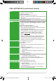
P8H61-M2/TPM/SI R2.0 specifications summary CPU Chipset Memory Expansion slots Graphics Storage LAN Audio LGA1155 socket for Intel® 3rd/2nd Generation Core™ i7 / i5 / i3 / Pentium® / Celeron® processors Supports 22/32nm CPU Supports Intel® Turbo Boost Technology 2.0 * The Intel® Turbo Boost Technology 2.0 support depends on the CPU types. ** Refer to www.asus.com for Intel® CPU support list. Intel® H61 Express Chipset 4 x DIMMs, max. 32GB, DDR3 2200 (O.C.) / 2000 (O.C.) / 1800 (O.C.) / 1600 (O.C.
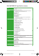
P8H61-M2/TPM/SI R2.0 specifications summary USB ASUS Special features Internal connectors Rear panel ports BIOS features Accessories Support DVD Form factor 10 x USB 2.0/1.
E7361_P8H61-M2-TPM-SI R2.
Chapter 1 Product introduction 1.1 Welcome! Thank you for buying an ASUS® P8H61-M2/TPM/SI R2.0 motherboard! The motherboard delivers a host of new features and latest technologies, making it another standout in the long line of ASUS quality motherboards! Before you start installing the motherboard, and hardware devices on it, check the items in your package with the list below. 1.2 Package contents Check your motherboard package for the following items. Motherboard ASUS P8H61-M2/TPM/SI R2.
Intel® H61 Express Chipset The Intel® H61 Express Chipset is the latest single-chipset design to support the new 1155 socket Intel® 3rd/2nd Generation Core™ i7 / Core™ i5 / Core™ i3 / Pentium® / Celeron® processors. It provides improved performance by utilizing serial point-to-point links, which allows increased bandwidth and stability. Dual-Channel DDR3 2200 (O.C.) / 2000 (O.C.) / 1800 (O.C.) / 1600 (O.C.
1.3.2 Innovative ASUS features Network iControl With a one-click on/off button, the software currently in use is set as top priority over all other network programs, dominating the network bandwidth with ease. Moreover, you can prioritize your favorite software easily by configuring profiles through the intutive user interface. Within the profile, programs can be pre-scheduled to run in a specific time period to avoid network clogging and long-waits on downloads.
GPU Boost GPU Boost overclocks the integrated GPU in real time for the best graphics performance. User-friendly UI facilitates flexible frequency and voltage adjustments. Its ability to deliver multiple overclocking profiles also provides rapid and stable system-level upgrades. EPU Energy Efficiency All Around Tap into the world’s first real-time PC power saving chip through the AI Suite II utility.
1.4 Before you proceed Take note of the following precautions before you install motherboard components or change any motherboard settings. • Unplug the power cord from the wall socket before touching any component. • Before handling components, use a grounded wrist strap or touch a safely grounded object or a metal object, such as the power supply case, to avoid damaging them due to static electricity. • Hold components by the edges to avoid touching the ICs on them.
1.5 Motherboard overview Before you install the motherboard, study the configuration of your chassis to ensure that the motherboard fits into it. Ensure that you unplug the power cord before installing or removing the motherboard. Failure to do so can cause you physical injury and damage motherboard components. 1.5.1 Placement direction 1.5.2 Screw holes When installing the motherboard, ensure that you place it into the chassis in the correct orientation.
1.5.3 Motherboard layout 1 2 3 2 4 5 22.4cm(8.8in) CPU_FAN KB_USB56 COM1 EPU DVI Super I/O Lithium Cell CMOS Power LPT 24.4cm(9.6in) CHA_FAN LAN_USB12 6 EATXPWR DDR3 DIMM_B2 (64bit, 240-pin module) USB3_E12 DDR3 DIMM_B1 (64bit, 240-pin module) LGA1155 VGA ASM 1443 DDR3 DIMM_A2 (64bit, 240-pin module) DDR3 DIMM_A1 (64bit, 240-pin module) ATX12V 1 AUDIO PCIEX16 64Mb BIOS P8H61-M2/TPM/SI R2.
1.6 Central Processing Unit (CPU) The motherboard comes with a surface mount LGA1155 socket designed for the Intel® 3rd/2nd Generation Core™ i7/ i5/ i3/ Pentium® / Celeron® processors. Unplug all power cables before installing the CPU. • Upon purchase of the motherboard, ensure that the PnP cap is on the socket and the socket contacts are not bent. Contact your retailer immediately if the PnP cap is missing, or if you see any damage to the PnP cap/socket contacts/motherboard components.
3. Lift the load lever in the direction of the arrow until the load plate is completely lifted. Load plate 4. Remove the PnP cap from the CPU socket by lifting the tab only. PnP cap 5. Position the CPU over the socket, ensuring that the gold triangle is on the bottom‑left corner of the socket, and then fit the socket alignment keys into the CPU notches. The CPU fits in only one correct orientation.
6. Apply some Thermal Interface Material to the exposed area of the CPU that the heatsink will be in contact with, ensuring that it is spread in an even thin layer. Some heatsinks come with preapplied thermal paste. If so, skip this step. The Thermal Interface Material is toxic and inedible. DO NOT eat it. If it gets into your eyes or touches your skin, wash it off immediately, and seek professional medical help. 7.
1.6.2 Installing the CPU heatsink and fan The Intel® LGA1155 processor requires a specially designed heatsink and fan assembly to ensure optimum thermal condition and performance. • When you buy a boxed Intel® processor, the package includes the CPU fan and heatsink assembly. If you buy a CPU separately, ensure that you use only Intel®‑certified multi‑directional heatsink and fan. • Your Intel® LGA1155 heatsink and fan assembly comes in a push-pin design and requires no tool to install.
3. Connect the CPU fan cable to the connector on the motherboard labeled CPU_FAN. CPU FAN PWM CPU FAN IN CPU FAN PWR GND CPU_FAN P8H61-M2/TPM/SI R2.0 P8H61-M2/TPM/SI R2.0 CPU fan connector Do not forget to connect the CPU fan connector! Hardware monitoring errors can occur if you fail to plug this connector. 1.6.3 Uninstalling the CPU heatsink and fan To uninstall the CPU heatsink and fan: 1. Disconnect the CPU fan cable from the connector on the motherboard. 2.
4. Carefully remove the heatsink and fan assembly from the motherboard. 5. Rotate each fastener clockwise to ensure correct orientation when reinstalling. 1.7 System memory 1.7.1 Overview DIMM_B1 DIMM_B2 DIMM_A1 DIMM_A2 This motherboard comes with four Double Data Rate 3 (DDR3) Dual Inline Memory Modules (DIMM) sockets. A DDR3 module has the same physical dimensions as a DDR2 DIMM but is notched differently to prevent installation on a DDR2 DIMM socket.
1.7.2 Memory configurations You may install 1GB, 2GB, 4GB, and 8GB unbuffered non‑ECC DDR3 DIMMs into the DIMM sockets. • You may install varying memory sizes in Channel A and Channel B. The system maps the total size of the lower-sized channel for the dual-channel configuration. Any excess memory from the higher-sized channel is then mapped for single-channel operation. • Always install DIMMs with the same CAS latency.
DDR3-2250 (O.C.) MHz capability SS/DS Chip Brand Vendors Part No. Kingston KHX2250C9D3T1K2/4GX(XMP) 4GB(2 x 2GB) DS Size DIMM socket support (Optional) 1 DIMM 2 DIMMs 4 DIMMs • • Chip NO. Timing Voltage - - - 1.65V Chip NO. Timing Voltage - 1.65V 1.65V 1.5V-1.7V 1.5V-1.7V DDR3-2200 (O.C.) MHz capability Vendors Part No.
DDR3-1600 (O.C.) MHz capability Vendors Part No. Size SS/DS Chip Brand Chip NO. Timing Voltage A-DATA Corsair Corsair Crucial G.SKILL G.SKILL G.SKILL G.SKILL Kingmax Kingmax Kingston Kingston AX3U1600GC4G9-2G(XMP) TR3X6G1600C8 G(XMP) CMX8GX3M4A1600C9(XMP) BL25664BN1608.
DDR3-1066 MHz capability (IVY Bridge CPU) Vendors Part No. Size SS/DS Crucial Crucial 1GB SS 2GB DS CT12864BA1067.8FF CT25664BA1067.16FF Chip Brand Micron Micron Chip NO.
1.7.3 Installing a DIMM Unplug the power supply before adding or removing DIMMs or other system components. Failure to do so can cause severe damage to both the motherboard and the components. 2 1. Press the retaining clips outward to unlock a DIMM socket. 2. Align a DIMM on the socket such that the notch on the DIMM matches the DIMM slot key on the socket. DIMM notch 1 1 DIMM slot key Unlocked retaining clip A DIMM is keyed with a notch so that it fits in only one direction.
1.8 Expansion slots In the future, you may need to install expansion cards. The following sub‑sections describe the slots and the expansion cards that they support. Unplug the power cord before adding or removing expansion cards. Failure to do so may cause you physical injury and damage motherboard components. 1.8.1 Installing an expansion card To install an expansion card: 1.
1.9 Jumpers Clear RTC RAM (3-pin CLRTC) This jumper allows you to clear the Real Time Clock (RTC) RAM in CMOS. You can clear the CMOS memory of date, time, and system setup parameters by erasing the CMOS RTC RAM data. The onboard button cell battery powers the RAM data in CMOS, which include system setup information such as system passwords. CLRTC 1 2 2 Normal (Default) Clear RTC 3 P8H61-M2/TPM/SI R2.0 P8H61-M2/TPM/SI R2.0 Clear RTC RAM To erase the RTC RAM: 1.
1.10 Connectors 1.10.1 Rear panel ports 1 1. 2. 3 4 2 10 9 8 5 6 7 PS/2 keyboard/mouse combo port. This port is for a PS/2 keyboard/mouse. LAN (RJ-45) port. This port allows connection to a Local Area Network (LAN) through a network hub. Refer to the table below for the LAN port LED indications.
6. USB 2.0 ports 1 and 2. These two 4-pin Universal Serial Bus (USB) ports are available for connecting USB 2.0 devices. 7. USB 2.0 ports 3 and 4. These two 4-pin Universal Serial Bus (USB) ports are available for connecting USB 2.0 devices. 8. Video Graphics Adapter (VGA) port. This 15-pin port is for a VGA monitor or other VGA-compatible devices. 9. DVI-D port. This port is for any DVI-D compatible device and is HDCP compliant allowing playback of HD DVD, Blu-ray, and other protected content. 10.
2. CPU and Chassis fan connectors (4-pin CPU_FAN, 3-pin CHA_FAN) Connect the fan cables to the fan connectors on the motherboard, ensuring that the black wire of each cable matches the ground pin of the connector. CPU FAN PWM CPU FAN IN CPU FAN PWR GND CPU_FAN CHA_FAN P8H61-M2/TPM/SI R2.0 GND +12V Rotation P8H61-M2/TPM/SI R2.0 Fan connectors DO NOT forget to connect the fan cables to the fan connectors. Insufficient air flow inside the system may damage the motherboard components.
4. LPT connector (26-1 pin LPT) The LPT (Line Printing Terminal) connector supports devices such as a printer. LPT is standardized as IEEE 1284, which is the parallel port interface on IBM PC-compatible computers. LPT P8H61-M2/TPM/SI R2.0 GND GND GND GND GND GND GND GND SLIN# INIT# ERR# AFD SLCT PE BUSY ACK# PD7 PD6 PD5 PD4 PD3 PD2 PD1 PD0 STB# PIN 1 P8H61-M2/TPM/SI R2.0 parallel port connector 5. System panel connector (10-1 pin F_PANEL) This connector supports several chassis-mounted functions.
Serial ATA 3.0 Gb/s connectors (7-pin SATA3G_1-4) These connectors connect to Serial ATA 3.0 Gb/s hard disk drives and optical drives via Serial ATA 3.0 Gb/s signal cables. SATA3G_2 GND RSATA_RXP4 RSATA_RXN4 GND RSATA_TXN4 RSATA_TXP4 GND SATA3G_4 P8H61-M2/TPM/SI R2.0 GND RSATA_TXP1 RSATA_TXN1 GND RSATA_RXN1 RSATA_RXP1 GND SATA3G_1 GND RSATA_TXP3 RSATA_TXN3 GND RSATA_RXN3 RSATA_RXP3 GND SATA3G_3 GND RSATA_RXP2 RSATA_RXN2 GND RSATA_TXN2 RSATA_TXP2 GND 6. P8H61-M2/TPM/SI R2.0 Intel® SATA 3.
USB 2.0 connectors (10-1 pin USB78, USB910) These connectors are for USB 2.0 ports. Connect the USB module cable to any of these connectors, then install the module to a slot opening at the back of the system chassis. These USB connectors comply with USB 2.0 specification that supports up to 480Mbps connection speed. USB78 PIN 1 PIN 1 USB+5V USB_P9USB_P9+ GND P8H61-M2/TPM/SI R2.0 USB+5V USB_P8USB_P8+ GND NC USB+5V USB_P10USB_P10+ GND NC USB910 USB+5V USB_P7USB_P7+ GND 8. P8H61-M2/TPM/SI R2.
Digital audio connector (4-1 pin SPDIF_OUT) SPDIFOUT GND This connector is for an additional Sony/Philips Digital Interface (S/PDIF) port. +5V 10. P8H61-M2/TPM/SI R2.0 SPDIF_OUT P8H61-M2/TPM/SI R2.0 Digital audio connector The S/PDIF module is purchased separately. Chapter 1: Product introduction E7361_P8H61-M2-TPM-SI R2.
1.11 Software support 1.11.1 Installing an operating system This motherboard supports Windows® XP / Vista / 7 Operating Systems (OS). Always install the latest OS version and corresponding updates to maximize the features of your hardware. • Motherboard settings and hardware options vary. Refer to your OS documentation for detailed information.
Chapter 2 BIOS information 2.1 Managing and updating your BIOS Save a copy of the original motherboard BIOS file to a USB flash disk in case you need to restore the BIOS in the future. Copy the original motherboard BIOS using the ASUS Update utility. 2.1.1 ASUS Update utility The ASUS Update is a utility that allows you to manage, save, and update the motherboard BIOS in Windows® environment. • ASUS Update requires an Internet connection either through a network or an Internet Service Provider (ISP).
The ASUS Update utility is capable of updating itself through the Internet. Always update the utility to avail all its features. Updating from a BIOS file a. 3. b. Select Update BIOS from file, then click Next. Locate the BIOS file from the Open window, then click Open. Follow the onscreen instructions to complete the updating process. 2.1.2 ASUS EZ Flash 2 The ASUS EZ Flash 2 feature allows you to update the BIOS without using an OS‑based utility.
3. 4. 5. 6. Press to switch to the Drive field. Press the Up/Down arrow keys to find the USB flash disk that contains the latest BIOS, and then press . Press to switch to the Folder Info field. Press the Up/Down arrow keys to find the BIOS file, and then press to perform the BIOS update process. Reboot the system when the update process is done. • This function supports USB flash disks with FAT 32/16 format and single partition only.
2.1.4 ASUS BIOS Updater The ASUS BIOS Updater allows you to update BIOS in DOS environment. This utility also allows you to copy the current BIOS file that you can use as a backup when the BIOS fails or gets corrupted during the updating process. The succeeding utility screens are for reference only. The actual utility screen displays may not be same as shown. Before updating BIOS 1. 2. Prepare the motherboard support DVD and a USB flash drive in FAT32/16 format and single partition.
Updating the BIOS file To update the BIOS file using BIOS Updater 1. At the FreeDOS prompt, type bupdater /pc /g and press . D:\>bupdater /pc /g 2. The BIOS Updater screen appears as below. ASUSTek BIOS Updater for DOS V1.07 Current ROM BOARD: P8H61-M2/TPM/SI R2.0 VER: 0304 DATE: 04/20/2012 Update ROM BOARD: Unknown VER: Unknown DATE: Unknown PATH: A:\ H61M2TR.CAP A: Note [Enter] Select or Load [Up/Down/Home/End] Move 3.
2.2 BIOS setup program Use the BIOS Setup program to update the BIOS or configure its parameters. The BIOS screens include navigation keys and brief online help to guide you in using the BIOS Setup program. Entering BIOS Setup at startup To enter BIOS Setup at startup: • Press during the Power-On Self Test (POST). If you do not press , POST continues with its routines. Entering BIOS Setup after POST To enter BIOS Setup after POST: • Press ++ simultaneously.
EZ Mode By default, the EZ Mode screen appears when you enter the BIOS setup program. The EZ Mode provides you an overview of the basic system information, and allows you to select the display language, system performance mode and boot device priority. To access the Advanced Mode, click Exit/Advanced Mode or press Esc, then select Advanced Mode or press F7 hot key for the advanced BIOS settings. The default screen for entering the BIOS setup program can be changed.
Advanced Mode The Advanced Mode provides advanced options for experienced end-users to configure the BIOS settings. The figure below shows an example of the Advanced Mode. Refer to the following sections for the detailed configurations. To access the EZ Mode, click Exit, then select ASUS EZ Mode.
Menu items The highlighted item on the menu bar displays the specific items for that menu. For example, selecting Main shows the Main menu items. The other items (Ai Tweaker, Advanced, Monitor, Boot, Tool, and Exit) on the menu bar have their respective menu items. Back button This button appears when entering a submenu. Press or use the USB mouse to click this button to return to the previous menu screen.
2.3 Main menu The Main menu screen appears when you enter the Advanced Mode of the BIOS Setup program. The Main menu provides you an overview of the basic system information, and allows you to set the system date, time, language, and security settings. 2.3.1 System Language [English] Allows you to choose the BIOS language version from the options. Configuration options: [English] [Français] [Español] [Deutsch] [Русский] 2.3.2 System Date [Day xx/xx/xxxx] 2.3.3 System Time [xx:xx:xx] 2.3.
Administrator Password If you have set an administrator password, we recommend that you enter the administrator password for accessing the system. Otherwise, you might be able to see or change only selected fields in the BIOS setup program. To set an administrator password: 1. Select the Administrator Password item and press . 3. Confirm the password when prompted. 2. From the Create New Password box, key in a password, then press . To change an administrator password: 1. 2. 3. 4.
2.4 Ai Tweaker menu The Ai Tweaker menu items allow you to configure overclocking-related items. Be cautious when changing the settings of the Ai Tweaker menu items. Incorrect field values can cause the system to malfunction. The configuration options for this section vary depending on the CPU and DIMM model you installed on the motherboard. 2.4.1 ASUS MultiCore Enhancement [Enabled] 2.4.
2.4.4 DRAM Timing Control The sub-items in this menu allow you to set the DRAM timing control features. Use the <+> and <-> keys to adjust the value. To restore the default setting, type [auto] using the keyboard and press . Changing the values in this menu may cause the system to become unstable! If this happens, revert to the default settings. 2.4.5 CPU Power Management The sub-items in this menu allow you to set the CPU ratio and features.
2.5 Advanced menu The Advanced menu items allow you to change the settings for the CPU and other system devices. Be cautious when changing the settings of the Advanced menu items. Incorrect field values can cause the system to malfunction. 2.5.1 Trusted Computing This item appears only when a TPM module is connected to the motherboard and allows you to change TPM settings. TPM Support [Disabled] Allows you to enable or disable TPM support. Configuration options: [Disabled] [Enabled] 2.5.
Active Processor Cores [All] Allows you to choose the number of CPU cores to activate in each processor package. Configuration options: [All] [1] [2] [3] Limit CPUID Maximum [Disabled] [Enabled] Allows legacy operating systems to boot even without support for CPUs with extended CPUID functions. [Disabled] Disables this function. Execute Disable Bit [Enabled] [Enabled] [Disabled] Enables the No-Execution Page Protection Technology. Forces the XD feature flag to always return to zero (0).
CPU C3 Report [Auto] Allows you to disable or enable the CPU C3 report to OS. Configuration options: [Auto] [Enabled] [Disabled] CPU C6 Report [Auto] Allows you to disable or enable the CPU C6 report to OS. Configuration options: [Auto] [Enabled] [Disabled] 2.5.3 PCH Configuration High Precision Timer [Enabled] Allows you to enable or disable the High Precision Event Timer.
2.5.4 SATA Configuration While entering Setup, the BIOS automatically detects the presence of SATA devices. The SATA Port items show Empty if no SATA device is installed to the corresponding SATA port. SATA Mode Selection [IDE] Allows you to set the SATA configuration. [Disabled] Disables the SATA function. [IDE] Set to [IDE] when you want to use the Serial ATA hard disk drives as Parallel ATA physical storage devices.
iGPU Multi-Monitor [Disabled] Allows you to enable or disable the Lucid Virtu support for both the integrated and discrete graphics. The iGPU shared memory size will be fixed at 64MB. Configuration options: [Disabled] [Enabled] 2.5.6 USB Configuration The items in this menu allow you to change the USB-related features. The USB Devices item shows the auto-detected values. If no USB device is detected, the item shows None.
Serial Port Configuration The sub-items in this menu allow you to set the serial port configuration. Serial Port [Enabled] Allows you to enable or disable the serial port (COM). Configuration options: [Enabled] [Disabled] Change Settings [IO=3F8h; IRQ=4] Allows you to select the Serial Port base address.
Power On By Ring [Disabled] [Disabled] [Enabled] Disables Ring to generate a wake event. Enables Ring to generate a wake event. Power On By RTC [Disabled] [Disabled] [Enabled] 2.5.9 Disables RTC to generate a wake event. When set to [Enabled], the items RTC Alarm Date (Days) and Hour/ Minute/Second will become user-configurable with set values. Network Stack Network Stack [Disable Link] This item allows user to disable or enable the UEFI network stack.
2.6 Monitor menu The Monitor menu displays the system temperature/power status, and allows you to change the fan settings. Scroll down to display the following items: 2.6.1 CPU Temperature / MB Temperature ������������� [xxxºC/xxxºF] The onboard hardware monitor automatically detects and displays the CPU and motherboard temperatures. Select Ignore if you do not wish to display the detected temperatures. 2.6.
2.6.4 [Disabled] [Enabled] CPU Q-Fan Control [Enabled] Disables the CPU Q-Fan control feature. Enables the CPU Q-Fan control feature. CPU Fan Speed Low Limit [200 RPM] This item appears only when you enable the CPU Q-Fan Control feature and allows you to disable or set the CPU fan warning speed.
Chassis Fan Profile [Standard] This item appears only when you enable the Chassis Q-Fan Control feature and allows you to set the appropriate performance level of the chassis fan. [Standard] Sets to [Standard] to make the chassis fan automatically adjust depending on the chassis temperature. [Silent] Sets to [Silent] to minimize the fan speed for quiet chassis fan operation. [Turbo] Sets to [Turbo] to achieve maximum chassis fan speed.
2.7 Boot menu The Boot menu items allow you to change the system boot options. UEFI BIOS Utility - Advanced Mode Ai Tweaker Main Exit Advanced Bootup NumLock State Full Screen Logo Wait For ‘F1’ If Error Option ROM Messages Monitor On Boot Tool Select the keyboard NumLock state Enabled Enabled Force BIOS Setup Mode EZ Mode UEFI/Legacy Boot Enabled both...
2.7.4 [Force BIOS] Option ROM Messages [Force BIOS] [Keep Current] The third-party ROM messages will be forced to display during the boot sequence. The third-party ROM messages will be displayed only if the third-party manufacturer had set the add-on device to do so. 2.7.5 Setup Mode [EZ Mode] 2.7.6 UEFI/Legacy Boot [Enabled both UEFI and Legacy] 2.7.7 PCI ROM Priority [Legacy ROM] 2.7.
2.8 Tools menu The Tools menu items allow you to configure options for special functions. Select an item then press to display the submenu. EFI BIOS Utility - Advanced Mode Ai Tweaker Main Advanced Exit Monitor Boot Tool Be used to update BIOS > ASUS EZ Flash 2 Utility > ASUS SPD Information > ASUS O.C. Profile 2.8.1 ASUS EZ Flash 2 Utility Allows you to run ASUS EZ Flash 2. Press [Enter] to launch the ASUS EZ Flash 2 screen. For more details, refer to section 2.1.2 ASUS EZ Flash 2. 2.
2.9 Exit menu The Exit menu items allow you to load the optimal default values for the BIOS items, and save or discard your changes to the BIOS items. You can access the EZ Mode from the Exit menu. Exit Load Optimized Defaults Save Changes & Reset Discard Changes & Exit ASUS EZ Mode Launch EFI Shell from filesystem device Load Optimized Defaults This option allows you to load the default values for each of the parameters on the Setup menus.
2-28 E7361_P8H61-M2-TPM-SI R2.
Appendices Notices Federal Communications Commission Statement This device complies with Part 15 of the FCC Rules. Operation is subject to the following two conditions: • This device may not cause harmful interference. • This device must accept any interference received including interference that may cause undesired operation. This equipment has been tested and found to comply with the limits for a Class B digital device, pursuant to Part 15 of the FCC Rules.
Canadian Department of Communications Statement This digital apparatus does not exceed the Class B limits for radio noise emissions from digital apparatus set out in the Radio Interference Regulations of the Canadian Department of Communications. This class B digital apparatus complies with Canadian ICES-003.
ASUS contact information ASUSTeK COMPUTER INC. Address Telephone Fax E-mail Web site Technical Support Telephone Online support 15 Li-Te Road, Peitou, Taipei, Taiwan 11259 +886-2-2894-3447 +886-2-2890-7798 info@asus.com.tw www.asus.com.tw +86-21-38429911 support.asus.
E7361_P8H61-M2-TPM-SI R2.0_Manua3 3 5/16/12 1:45:13 PM (510)739-3777/(510)608-4555 800 Corporate Way, Fremont, CA 94539. Asus Computer International Signature : Date : Representative Person’s Name : May , 2012 Steve Chang / President This device complies with part 15 of the FCC Rules.