User Guide Motherboard P4BP-MX
E1534 Checklist First Edition February 2004 Copyright © 2004 ASUSTeK COMPUTER INC. All Rights Reserved. No part of this manual, including the products and software described in it, may be reproduced, transmitted, transcribed, stored in a retrieval system, or translated into any language in any form or by any means, except documentation kept by the purchaser for backup purposes, without the express written permission of ASUSTeK COMPUTER INC. (“ASUS”).
Contents Features Notices ............................................................................................ v Safety information .......................................................................... vi About this guide ............................................................................. vii Conventions used in this guide ............................................ vii Typography ...........................................................................
Contents Safeguards Chapter 2: BIOS information 2.1 2.2 2.3 2.4 2.5 2.6 2.7 Managing and updating your BIOS .................................... 2-2 2.1.1 Using ASUS EZ Flash to update the BIOS ............ 2-2 2.1.2 Using AFLASH to update the BIOS ....................... 2-3 2.1.3 Recovering the BIOS with CrashFree BIOS .......... 2-7 BIOS Setup program .......................................................... 2-8 2.2.1 BIOS menu bar ...................................................... 2-8 2.2.
Notices Federal Communications Commission Statement This device complies with Part 15 of the FCC Rules. Operation is subject to the following two conditions: • This device may not cause harmful interference, and • This device must accept any interference received including interference that may cause undesired operation. The use of shielded cables for connection of the monitor to the graphics card is required to assure compliance with FCC regulations.
Safety information Electrical safety • To prevent electrical shock hazard, disconnect the power cable from the electrical outlet before relocating the system. • When adding or removing devices to or from the system, ensure that the power cables for the devices are unplugged before the signal cables are connected. If possible, disconnect all power cables from the existing system before you add a device.
About this guide Conventions used in this guide To make sure that you perform certain tasks properly, take note of the following symbols used throughout this manual. WARNING: Information to prevent injury to yourself when trying to complete a task. CAUTION: Information to prevent damage to the components when trying to complete a task. IMPORTANT: Information that you MUST follow to complete a task. NOTE: Tips and additional information to aid in completing a task.
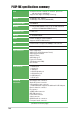
P4BP-MX specifications summary CPU Socket 478 for Intel® Pentium® 4 / Celeron® processors with speeds up to 3.
BIOS features 2Mb Flash ROM, Award BIOS, TCAV, PnP, DMI2.0, WfM2.0, SM BIOS 2.3 Industry standard PCI 2.2, USB 2.0 Form Factor MicroATX form factor: 9.6 in x 8.6 in Support CD contents Device drivers ASUS PC Probe ASUS Live Update Utility Trend Micro™ PC-cillin™ anti-virus software * Specifications are subject to change without notice.
x
Chapter 1 This chapter describes the features of the motherboard. It includes brief descriptions of the motherboard components, and illustrations of the layout, jumper settings, and connectors.
1.1 Welcome! Thank you for buying the ASUS® P4BP-MX motherboard! The motherboard delivers a host of new features and latest technologies making it another standout in the long line of ASUS quality motherboards! The motherboard combines the powers of the Intel® Pentium® 4 processor and the Intel® 845GV chipset to set a new benchmark for an effective desktop platform solution. Supporting up to 2GB of system memory with PC2700/PC2100 DDR SDRAM, high-resolution graphics via an AGP 8X slot, USB 2.
1.3 Special features 1.3.1 Product Highlights Latest processor technology The motherboard comes with a 478-pin surface mount, Zero Insertion Force (ZIF) socket for the Intel® Pentium® 4 processor in the 478-pin package with 512/256KB L2 cache on 0.13 micron process. This motherboard supports 533/400 MHz system front side bus that allows 4.3GB/s and 3.2GB/s data transfer rates, respectively. The motherboard also supports the Intel® Hyper-Threading Technology.
1.3.2 Unique ASUS features CrashFree BIOS This feature allows you to restore the original BIOS data froma bootable floppy disk in case the BIOS codes and data are corrupted. This protection eliminates the need to buy a replacement ROM chip. See page 2-7. ASUS EZ Flash BIOS With the ASUS EZ Flash, you can easily update the system BIOS even before loading the operating system. No need to use a DOS-based utility or boot from a floppy disk. See page 2-2.
1.4 Before you proceed Take note of the following precautions before you install motherboard components or change any motherboard settings. 1. 2. 3. 4. 5. Unplug the power cord from the wall socket before touching any component. Use a grounded wrist strap or touch a safely grounded object or discharge any static electricity by touching the metal surface of the system chassis. Hold components by the edges to avoid touching the ICs on them.
1.5 Motherboard overview 1.5.1 Motherboard layout 21.9cm (8.6in) PS/2KBMS T: Mouse B: Keyboard Super I/O CPUFAN1 Socket 478 USBPWR_34 KBPWR1 Intel 845GV Graphic Memory Controller Hub (GMCH) USBPWR_12 USB2.0 Top: RJ-45 ATX12V1 T: USB20_1 B: USB20_2 FLOPPY1 2 3 ATX Power Connector 0 1 24.4cm (9.
1.5.2 Placement direction When installing the motherboard, make sure that you place it into the chassis in the correct orientation. The edge with external ports goes to the rear part of the chassis as indicated in the image below. 1.5.3 Screw holes Place six (6) screws into the holes indicated by circles to secure the motherboard to the chassis. Do not overtighten the screws! Doing so may damage the motherboard.
1.6 Central Processing Unit (CPU) 1.6.1 Overview The motherboard comes with a surface mount 478-pin Zero Insertion Force (ZIF) socket designed for the Intel® Pentium® 4 processor. Take note of the marked corner (with gold triangle) on the CPU. This mark should match a specific corner on the socket to ensure correct installation.
1.6.2 Installing the CPU Follow these steps to install a CPU. 1. Locate the 478-pin ZIF socket on the motherboard. 90º~100º angle 2. Unlock the socket by pressing the lever sideways, then lift it up to a 90°100° angle. Socket Lever Make sure that the socket lever is lifted up to 90°-100° angle; otherwise, the CPU does not fit in completely. 3. Position the CPU above the socket such that its marked corner matches the base of the socket lever. Gold Mark 4.
1.7 System memory 1.7.1 DIMM sockets location You can install 64MB, 256MB, 512MB, and 1GB DDR DIMMs into the DIMM sockets of this motherboard. The following figure illustrates the location of the DDR DIMM sockets. 80 Pins 104 Pins P4BP-MX P4BP-MX 184-Pin DDR DIMM Sockets Make sure to unplug the power supply before adding or removing DIMMs or other system components. Failure to do so may cause severe damage to both the motherboard and the components. 1.7.
1.8 Expansion slots To install and configure an expansion card: 1. Install an expansion card following the instructions that came with the chassis. 2. Turn on the system and change the necessary BIOS settings, if any. See Chapter 2 for BIOS information. 3. Assign an IRQ to the card. Refer to the tables next page. 4. Install the drivers and/or software applications for the expansion card according to the card documentation. 1.8.
1.8.3 PCI slots The PCI slots support PCI cards such as a LAN card, SCSI card, USB card, and other cards that comply with PCI specifications.
1.9 Jumpers 1. Clear RTC RAM (J1) This jumper allows you to clear the Real Time Clock (RTC) RAM in CMOS. You can clear the CMOS memory of date, time, and system setup parameters by erasing the CMOS RTC RAM data. The RAM data in CMOS, that include system setup information such as system passwords, is powered by the onboard button cell battery. To erase the RTC RAM: 1. Turn OFF the computer and unplug the power cord. 2. Move the jumper cap from pins 1-2 (default) to pins 2-3.
2. Keyboard power (3-pin KBPWR1) This jumper allows you to enable or disable the keyboard wake-up feature. Set this jumper to pins 2-3 (+5VSB) if you wish to wake up the computer when you press a key on the keyboard. This feature requires an ATX power supply that can supply at least 1A on the +5VSB lead, and a corresponding setting in the BIOS. KBPWR1 3 2 2 1 +5V +5VSB (Default) P4BP-MX P4BP-MX Keyboard Power Setting 3.
1.10 Connectors This section describes and illustrates the motherboard rear panel and internal connectors. 1.10.1 Rear panel connectors 1 2 3 4 5 6 11 10 9 8 7 1. PS/2 mouse port. This green 6-pin connector is for a PS/2 mouse. 2. Parallel port. This 25-pin port connects a parallel printer, a scanner, or other devices. 3. RJ-45 port. This port allows connection to a Local Area Network (LAN) through a network hub. 4. Line In jack.
1.10.2 Internal connectors 1. IDE connectors (40-1 pin PRI_IDE, SEC_IDE) This connector supports the provided Ultra DMA 100/66 IDE hard disk ribbon cable. Connect the cable’s blue connector to the primary (recommended) or secondary IDE connector, then connect the gray connector to the Ultra DMA 100/66 slave device (hard disk drive) and the black connector to the Ultra DMA 100/66 master device. Follow the hard disk drive documentation when setting the device in master or slave mode.
3. ATX power connectors (20-pin ATX_POWER1, 4-pin ATX12V1) These connectors connect to an ATX 12V power supply. The plugs from the power supply are designed to fit these connectors in only one orientation. Find the proper orientation and push down firmly until the connectors completely fit. In addition to the 20-pin ATX power connector, this motherboard requires that you connect the 4-pin ATX +12V power plug to provide sufficient power to the CPU.
5. CPU and chassis fan connectors (3-pin CPUFAN2, CHASFAN1) The fan connectors support cooling fans of 350mA~740mA (8.88W max.) or a total of 1A~2.22A (26.64W max.) at +12V. Connect the fan cables to the fan connectors on the motherboard, making sure that the black wire of each cable matches the ground pin of the connector. CPUFAN1 GND +12V Rotation CHASFAN1 Rotation +12V GND P4BP-MX P4BP-MX 12-Volt Cooling Fan Power Do not forget to connect the fan cables to the fan connectors.
7. Front panel audio connector (10-1 pin IAPANEL1) This is an interface for the front panel cable that allows convenient connection and control of audio devices. Be default, the pins labeled LINE OUT_R/BLINE_OUT_R and the pins LINE OUT_L/BLINE_OUT_L are shorted with jumper caps. Remove the caps only when you are connecting the front panel audio cable. IAPANEL1 P4BP-MX MIC2 MICPWR Line out_R NC AGND +5VA BLINE_OUT_R Line out_L BLINE_OUT_L P4BP-MX Front Panel Audio Connector 8.
9. GAME/MIDI connector (16-1 pin GAME1) +5V J1B2 J1CY GND GND J1CX J1B1 +5V This connector supports a GAME/MIDI module. If a GAME/MIDI module is available, connect the GAME/MIDI cable to this connector. The GAME/MIDI port on the module connects a joystick or a game pad for playing games, and MIDI devices for playing or editing audio files. P4BP-MX MIDI_IN J2B2 J2CY MIDI_OUT J2CX J2B1 +5V GAME1 P4BP-MX Game Connector The GAME/MIDI module is purchased separately. 10.
11. Infrared connector (10-pin IR1) Standard Infrared (SIR) Front View Back View GND IRTX +5V IRRX These connectors support an optional wireless transmitting and receiving infrared module. The module mounts to a small opening on the system chassis that supports this feature. You must also configure the UART2 Use As parameter in BIOS to set UART2 for use with IR.
13. System panel connector (20-1 pin PANEL) This connector accommodates several system front panel functions. Reset Ground PLED Keylock Ground ExtSMI# Ground PWR Ground +5 V Power LED Speaker Connector +5V Ground Ground Speaker Keyboard Lock Reset SW P4BP-MX SMI Lead P4BP-MX System Panel Connectors ATX Power Switch* * Requires an ATX power supply. • System Power LED Lead (2-pin PLED) This 2-pin connector connects to the system power LED. The LED lights up when you turn on the system power.
Chapter 2 This chapter tells how to change system settings through the BIOS Setup menus. Detailed descriptions of the BIOS parameters are also provided.
2.1 Managing and updating your BIOS The following utilities allow you to manage and update the motherboard Basic Input/Output System (BIOS) setup. 1. ASUS EZ Flash - Updates the BIOS using a floppy disk during POST. 2. ASUS AFLASH - Updates the BIOS using a bootable floppy disk in DOS mode. 3. ASUS CrashFree BIOS - Updates the BIOS using a bootable floppy disk. Refer to the corresponding sections for details on these utilities.
5. At the prompt, “Please Enter File Name for NEW BIOS: _”, type in the BIOS file name that you downloaded from the ASUS website, then press . EZ Flash will automatically access drive A to look for the file name that you typed. When found, the following message appears on screen. [BIOS Information in File] BIOS Version: P4BP-MX Boot Block WARNING! Continue to update the BIOS (Y/N)? _ If you accidentally typed in a wrong BIOS file name, the error message, “WARNING! File not found.” appears.
• • The AFLASH.EXE utility works only in DOS mode. It does not work with certain memory drivers that may be loaded when you boot from the hard drive. It is recommended that you reboot using a floppy disk. DO NOT copy AUTOEXEC.BAT and CONFIG.SYS to the disk. 4. Reboot the computer from the floppy disk. BIOS setup must specify “Floppy” as the first item in the boot sequence. 5.
Updating the BIOS Update the BIOS only if you are sure that the new BIOS revision will solve your problems. Careless updating may result to more problems with the motherboard! 1. Download an updated ASUS BIOS file from the ASUS website (www.asus.com) and save to the boot floppy disk you created earlier. 2. Boot from the floppy disk. 3. At the DOS prompt, type AFLASH then press . 4. From the Main Menu, type <2> then press . The Update BIOS Including Boot Block and ESCD screen appears. 5.
7. The utility starts to program the new BIOS information into the Flash ROM. The boot block is updated automatically only when necessary. When the programming is done, the message “Flashed Successfully” appears. 8. Follow the succeeding screen instructions to continue. DO NOT turn off the system while updating the BIOS. This may cause boot problems. Just repeat the process, and if the problem persists, load the original BIOS file you saved to the boot disk.
2.1.3 Recovering the BIOS with CrashFree BIOS The CrashFree BIOS auto recovery tool allows you to restore BIOS from a floppy disk that contains the BIOS file, in case the current BIOS on the motherboard fails or gets corrupted. • Prepare the floppy disk that contains the motherboard BIOS before proceeding with the BIOS update process. • If you have saved a copy of the original motherboard BIOS to a bootable floppy disk, you may also use this disk to restore the BIOS. See section “2.1.
2.2 BIOS Setup program Use the BIOS Setup program when you are installing a motherboard, reconfiguring your system, or prompted to “Run Setup”. This section explains how to configure your system using this utility. Even if you are not prompted to use the Setup program, you may want to change the configuration of your computer in the future. For example, you may want to enable the security password feature or make changes to the power management settings.
2.2.2 Legend bar At the bottom of the Setup screen is a legend bar. The keys in the legend bar allow you to navigate through the various setup menus. The following table lists the keys found in the legend bar with their corresponding functions.
Sub-menu Note that a right pointer symbol (as shown on the left) appears to the left of certain fields. This pointer indicates that you can display a sub-menu from this field. A sub-menu contains additional options for a field parameter. To display a sub-menu, move the highlight to the field and press . The sub-menu appears. Use the legend keys to enter values and move from field to field within a sub-menu as you would within a menu. Use the key to return to the main menu.
Legacy Diskette A [1.44M, 3.5 in.] Sets the type of floppy drive installed. Configuration options: [None] [360K, 5.25 in.] [1.2M , 5.25 in.] [720K , 3.5 in.] [1.44M, 3.5 in.] [2.88M, 3.5 in.] Floppy 3 Mode Support [Disabled] This is required to support older Japanese floppy drives. The Floppy 3 Mode feature allows reading and writing of 1.2MB (as opposed to 1.44MB) on a 3.5-inch diskette.
2.3.1 Primary and Secondary Master/Slave Type [Auto] Select [Auto] to automatically detect an IDE hard disk drive. If automatic detection is successful, Setup automatically fills in the correct values for the remaining fields on this sub-menu. If automatic detection fails, select [User Type HDD] to manually enter the IDE hard disk drive parameters. Refer to the next section for details.
If no drive is installed or if you are removing a drive and not replacing it, select [None]. Other options for the Type field are: [CD-ROM] - for IDE CD-ROM drives [LS-120] - for LS-120 compatible floppy disk drives [ZIP] - for ZIP-compatible disk drives [MO] - for IDE magneto optical disk drives [Other ATAPI Device] - for IDE devices not listed here After making your selections on this sub-menu, press key to return to the Main menu.
Multi-Sector Transfers [Maximum] This option automatically sets the number of sectors per block to the highest number that the drive supports. Note that when this field is automatically configured, the set value may not always be the fastest value for the drive. You may also manually configure this field. Refer to the documentation that came with the hard drive to determine the optimum value and set it manually. To make changes to this field, set the Type field to [User Type HDD].
Keyboard Auto-Repeat Rate [6/Sec] This controls the speed at which the system registers repeated keystrokes. Options range from 6 to 30 characters per second. Configuration options: [6/Sec] [8/Sec] [10/Sec] [12/Sec] [15/Sec] [20/Sec] [24/Sec] [30/Sec] Keyboard Auto-Repeat Delay [1/4 Sec] This field sets the time interval for displaying the first and second characters. Configuration options: [1/4 Sec] [1/2 Sec] [3/4 Sec] [1 Sec] 2.
CPU Level 1 Cache, CPU Level 2 Cache [Enabled] These fields allow you to choose from the default [Enabled] or choose [Disabled] to turn on or off the CPU Level 1 and Level 2 built-in cache. Configuration options: [Disabled] [Enabled] BIOS Update [Enabled] This field functions as an update loader integrated into the BIOS to supply the processor with the required data. When set to [Enabled], the BIOS loads the update on all processors during system bootup.
2.4.1 Chip Configuration SDRAM Configuration [By SPD] This parameter allows you to set the optimal timings for items 2–5, depending on the memory modules that you are using. The default setting is [By SPD], which configures items 2–5 by reading the contents in the SPD (Serial Presence Detect) device. The EEPROM on the memory module stores critical information about the module, such as memory type, size, speed, voltage interface, and module banks.
NTSC/PAL Preference [NTSC] This field allows you to select broadcast transmission and reception standards. Configuration options: [NTSC] [PAL] Internal AGP Turbo Mode [Disabled] This field allows you to choose from the default [Enabled] or choose [Disabled] to turn on or off the AGP Turbo Mode. Configuration options: [Enabled] [Disabled] Graphics Aperture Size [128MB] This feature allows you to select the size of mapped memory for AGP graphic data.
2.4.2 I/O Device Configuration Floppy Disk Access Control [R/W] When set to [Read Only], this parameter protects files from being copied to floppy disks by allowing reads from, but not writes to, the floppy disk drive. The default setting [R/W] allows both reads and writes. Configuration options: [R/W] [Read Only] Onboard Serial Port 1 [3F8H/IRQ4], Port 2 [2F8H/IRQ3] These fields allow you to set the addresses for the onboard serial connectors.
Onboard AC97 Audio Controller [Auto] [Auto] allows the BIOS to detect whether you are using any audio device. If an audio device is detected, the onboard audio controller is enabled; if no audio device is detected, the controller is disabled. If there are conflicts with the onboard audio controller, set the appropriate field to [Disabled]. Configuration options: [Disabled] [Auto] Onboard MIDI I/O [Disabled] This field allows you to select the I/O address for the MIDI port.
USB 2.0 Controller [Enabled] This field allows you to turn on or off the USB 2.0 controller. Configuration options: [Disabled] [Enabled] Primary VGA BIOS [PCI VGA Card] This field allows you to select primary graphics card or onboard VGA as the primary display BIOS. Configuration options: [PCI VGA Card] [Onboard VGA] Onboard LAN Controller [Enabled] This field allows you to enable or disable the onboard LAN controller. This item appears only when onboard LAN exist.
2.5 Power Menu The Power menu allows you to reduce power consumption. This feature turns off the video display and shuts down the hard disk after a period of inactivity. Power Management [User Defined] This field allows you to activate or deactivate the automatic power saving features. When set to [Disabled], the power management features do not function regardless of the other settings on this menu.
Even if installed, your screen saver does not display when you select [Blank Screen] for the above field. [V/H SYNC+Blank] blanks the screen and turns off vertical and horizontal scanning. Configuration options: [Blank Screen] [V/H SYNC+Blank] [DPMS Standby] [DPMS Suspend] [DPMS OFF] [DPMS Reduce ON] HDD Power Down [Disabled] Shuts down any IDE hard disk drives in the system after a period of inactivity as set in this user-configurable field. This feature does not affect SCSI hard drives.
2.5.1 Power Up Control AC Power Loss Restart [Disabled] This allows you to set whether or not to reboot the system after AC power loss. [Disabled] leaves your system off while [Enabled] reboots the system. [Previous State] sets the system back to the state it was before the power interruption. Configuration options: [Disabled] [Enabled] [Previous State] Wake/Power Up On Ext.
2.5.2 Hardware Monitor MB Temperature [xxxC/xxxF] CPU Temperature [xxxC/xxxF] The onboard hardware monitor automatically detects and displays the motherboard and CPU temperatures. CPU Fan Speed [xxxxRPM] or [N/A] Chassis Fan Speed [xxxxRPM] or [N/A] The onboard hardware monitor automatically detects and displays the CPU and chassis fan speeds in rotations per minute (RPM). If any of the fans is not connected to the motherboard, that field shows N/A. VCORE Voltage, +3.
2.6 Boot Menu Boot Sequence The Boot menu allows you to select four types of boot devices using the up and down arrow keys. By using the <+> or key, you can promote devices and by using the <-> key, you can demote devices. Promotion or demotion of devices alters the priority which the system uses to boot device on system power up. Configuration fields include Removable Devices, IDE Hard Drive, ATAPI CD-ROM, and Other Boot Device.
Quick Power On Self Test [Enabled] This field speeds up the Power-On Self Test (POST) routine by skipping retesting several times. Configuration options: [Disabled] [Enabled] Boot Up Floppy Seek [Enabled] When enabled, the BIOS will seek the floppy disk drive to determine whether the drive has 40 or 80 tracks. Configuration options: [Disabled] [Enabled] Full Screen Logo [Enabled] Allows you to enable or disable the full screen logo display feature.
Exit Saving Changes Once you are finished making your selections, choose this option from the Exit menu to ensure the values you selected are saved to the CMOS RAM. The CMOS RAM is sustained by an onboard backup battery and stays on even when the PC is turned off. When you select this option, a confirmation window appears. Select [Yes] to save changes and exit.
Chapter 3 This chapter describes the contents of the support CD that comes with the motherboard package.
3.1 Install an operating system This motherboard supports Windows® 98SE/NT4.0/ME/2000/XP operating system (OS). Always install the latest OS version and corresponding updates to maximize the features of your hardware. Motherboard settings and hardware options vary, so use the setup procedures presented in this chapter for general reference only. Refer to your OS documentation for more information. 3.
3.2.2 Drivers menu The drivers menu shows the available device drivers if the system detects installed devices. Install the necessary drivers to activate the devices. Intel Chipset Inf Update Program Click this item to load the installation wizard and install the Intel® Chipset update driver. Intel Application Accelerator Driver Click this item to load the installation wizard and install the Intel® Application Accelerator.
ASUS PC Probe This smart utility monitors the fan speed, CPU temperature, and system voltages, and alerts you on any detected problems. This utility helps you keep your computer at a healthy operating condition. Install ASUS Update This program allows you to download the latest version of the BIOS from the ASUS website. Before using the ASUS Update, make sure that you have an Internet connection so you can connect to the ASUS website. Installing ASUS Update also installs ASUS Mylogo™.