® P4T-EM Intel® 850 ATX Motherboard USER’S MANUAL
USER'S NOTICE No part of this manual, including the products and software described in it, may be reproduced, transmitted, transcribed, stored in a retrieval system, or translated into any language in any form or by any means, except documentation kept by the purchaser for backup purposes, without the express written permission of ASUSTeK COMPUTER INC. (“ASUS”).
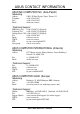
ASUS CONTACT INFORMATION ASUSTeK COMPUTER INC. (Asia-Pacific) Marketing Address: Telephone: Fax: Email: 150 Li-Te Road, Peitou, Taipei, Taiwan 112 +886-2-2894-3447 +886-2-2894-3449 info@asus.com.tw Technical Support MB/Others (Tel): +886-2-2890-7121 (English) Notebook (Tel): +886-2-2890-7122 (English) Desktop/Server (Tel):+886-2-2890-7123 (English) Fax: +886-2-2980-7698 Email: tsd@asus.com.tw WWW: www.asus.com.tw FTP: ftp.asus.com.tw/pub/ASUS Newsgroup: csnews.asus.com.
CONTENTS 1. INTRODUCTION ............................................................................. 7 1.1 How This Manual Is Organized .................................................. 7 1.2 Item Checklist ............................................................................. 7 2. FEATURES ........................................................................................ 8 2.1 The ASUS P4T-EM ..................................................................... 8 2.1.1 Core Specifications .
CONTENTS 4.6 4.7 5.1 5.2 4.5.1 Power Up Control .......................................................... 68 4.5.2 Hardware Monitor ......................................................... 69 Boot Menu ................................................................................ 70 Exit Menu ................................................................................. 72 Install Operating System ........................................................... 74 Start Windows ..........................
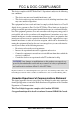
FCC & DOC COMPLIANCE This device complies with FCC Rules Part 15. Operation is subject to the following two conditions: • • This device may not cause harmful interference, and This device must accept any interference received, including interference that may cause undesired operation. This equipment has been tested and found to comply with the limits for a Class B digital device, pursuant to Part 15 of the FCC Rules.
1. INTRODUCTION 1. INTRODUCTION Manual / Checklist 1.1 How This Manual Is Organized This manual is divided into the following sections: 1. 2. 3. 4. 5. 6. 7. INTRODUCTION FEATURES HARDWARE SETUP BIOS SETUP SOFTWARE SETUP SOFTWARE REFERENCE APPENDIX Manual information and checklist Production information and specifications Intructions on setting up the motherboard.
2. FEATURES 2.1 The ASUS P4T-EM The ASUS P4T-EM motherboard is carefully designed for the demanding PC user who wants advanced features processed by the fastest processors. 2.1.1 Core Specifications • 2. FEATURES Core Specifications • • • • • • • 8 Intel Processor Support: Intel Socket 478 Pentium ® 4 / Northwood ™ processors, 1.4 to 2.0 GHz and higher. Intel 850 Chipset: Features the Intel® 850 chipset (82850 Memory Controller Hub, I/O Controller and Firmware Hub) with support for AGP 4X Mode, (1.
2. FEATURES 2.1.2 Connections • • • • • • • • • • • • • • • • • • CPU socket: 478-pin surface mount, ZIF socket mPGA478 B. PCI Expansion Slots: Provides two 32-bit PCI slots, (PCI 2.2 compliant) with no ISA, eliminating bottlenecks and system memory management issues. All PCI slots can support Bus Master PCI cards, such as SCSI or LAN cards. (PCI supports up to 133MB/s maximum throughput.
2. FEATURES 2.1.3 Optional Components • • • AC’97 Codec: The latest high-performance mini-chipset supports hi-fidelity 18-bit stereo, full duplex audio performance, up to four analog line inputs, two stereo outputs, and one mono output channel, 3D stereo enhancement. SPDIFOUT Connector: Enables digital audio output on multiple channels.. Onboard LAN: Optional LAN NIC for full networking capability. 2. FEATURES Options / Performance 2.1.
2. FEATURES • • • • • • • • Smartcard Reader Connector: This connector provides the convenience of PS/SC compatible Smart Card security plus support for a multitude of new financial, telephonic, and mobile access services. Intel Front Panel Connector: Supports an optional front panel for easy USB connectivity, control and monitoring of major PC functions. Fan Status Monitoring and Alarm: To prevent system overheat and system damage, the CPU and MAIN fans are monitored for speed and failure.
2. FEATURES 2.2 P4T-EM Motherboard Components See opposite page for locations. Location Processor Support Socket 478 for Pentium 4 Processors ....................................... 3 2. FEATURES MB Components Chipsets Intel 850 Memory Controller Hub (MCH) ............................... 5 Intel I/O Controller Hub 2 (ICH2) ......................................... 11 2Mbit Firmware Hub (FWH) ................................................. 13 Low Pin Count (LPC) Super Multi-I/O Chipset ..................
2. FEATURES 2.2.1 Component Locations 1 2 3 4 5 6 7 8 2.
3. HARDWARE SETUP 3.1 P4T-EM Motherboard Layout 24.4cm (9.
3.
3. HARDWARE SETUP 3.3 Hardware Setup Procedure IMPORTANT: Due to Pentium 4 CPU’s power consumption requirement, an ATX12V power supply is recommended for this motherboard. For typical system configurations, an ATX12V power supply that can supply at least 230W and at least 8.5A on the +12V lead is required. For heavily-loaded configurations, an ATX12V power supply of 300W may be required. Complete the following steps before using your computer: 1. Check motherboard settings 2. Install memory modules 3.
3. HARDWARE SETUP 1) Motherboard Frequency Settings (SW1) The motherboard frequency is adjusted through the DIP switches. The white block represents the switch’s position. The illustration below shows all the switches in the OFF position. ON 1 2 3 4 5 SW1 ON OFF P4T-EM ® 3. H/W SETUP Motherboard Settings P4T-EM DIP Switches 1. Frequency Selection 2. Frequency Selection 3. Frequency Selection 4. Frequency Selection 5. Frequency Selection.
3. HARDWARE SETUP ® 3. H/W SETUP Motherboard Settings P4T-EM CPU External Frequency Selection Frequency Table CPU AGP 100 66 103 68 105 70 110 73 PCI 33 34 35 36 1 [ON] [OFF] [ON] [ON] CPU 105.0MHz AGP 70.0MHz PCI 35.0MHz 2 [OFF] [OFF] [ON] [OFF] DSW 3 [ON] [ON] [OFF] [OFF] 1 2 3 4 5 ON 103.0MHz 68.0MHz 34.0MHz 1 2 3 4 5 ON P4T-EM 1 2 3 4 5 CPU 100.0MHz AGP 66.0MHz PCI 33.
3. HARDWARE SETUP 3. H/W SETUP Motherboard Settings 4) USB Device Wake-up (USBPWR) The jumpers are set to +5V as the default to allow wake up from the S1 sleep state (CPU stopped; RAM refreshed; system running in low power mode) using the connected USB devices. Set the jumpers to +5VSB to allow wake up from S3 sleep state (no power to CPU; RAM in slow refresh; power supply in reduced power mode).
3. HARDWARE SETUP 6) USB2 / CNRUSB Selection (J3-J3+, OC3) The CNR slot can support an optional USB hub CNR card. Three jumpers are used to control selection of USB or CNR functions: J3-, J3+ and OC3. The factory default setting is for standard USB2 control. If a USB hub CNR card is used, reset these jumpers to CNRUSB setting shown below. P4T-EM OC3 J3J3+ OC3 J3J3+ IMPORTANT! Always set all three jumpers accordingly when selecting a device. 3 2 2 1 USB2 3.
3. HARDWARE SETUP 3.5 System Memory NOTE: No hardware or BIOS setup is required after adding or removing memory. This motherboard has four 184-pin Rambus Inline Memory Modules (RIMM) sockets. These sockets support 64Mbit, 128Mbit, and 256Mbit Direct RDRAM technologies.
3. HARDWARE SETUP 3.5.1 Installing Memory The memory module (RIMM) will fit in only one orientation. IMPORTANT: Do not touch the memory module’s connectors. Handle the module only by the edges. RIMM Sockets P4T-EM RIMM with Heat Spreader ® 3. H/W SETUP System Memory P4T-EM 184-Pin RIMM Sockets C-RIMM 1. Make sure that the notch keys in the module are aligned with the small ribs inside the RIMM sockets.
3. HARDWARE SETUP 3.6 Central Processing Unit (CPU) The motherboard provides a ZIF Socket 478, for CPU installation. A fan and heatsink should be attached to the CPU to prevent overheating. Purchase and install a fan and heatsink before turning on the system. Gold Arrow P4T-EM ® 1. Locate the Socket 478 and open it by pulling the lever gently sideways away from the socket. Then lift the lever upwards. The socket lever must be fully opened (90 to 100 degrees). 90 - 100 2.
3. HARDWARE SETUP 3.6.1 Installing the Heatsink and Fan The Intel® Pentium® 4 478 / Northwood Processor comes complete with a specially designed heatsink and fan assembly to ensure optimum thermal condition and performance. If a CPU is purchased separately, only use an Intel certified heatsink and fan. Step 1: Mount the Heatsink Place the heatsink on top of the installed CPU. Make sure that the heatsink fits properly on the retention module base.
3. HARDWARE SETUP Step 2: Mount the Fan Position the fan with the retention mechanism on top of the heatsink. Align and snap the four hooks of the retention mechanism to the holes on each corner of the module base. Carefully fit the fan and retention mechanism assembly perfectly to the heatsink and module base, otherwise you cannot snap the hooks into the holes. Keep the retention locks lifted upward while fitting the retention mechanism to the module base. Retention Hole 3.
3. HARDWARE SETUP Step 3: Lock the Retention Mechanism Push down the locks on the retention mechanism to secure the heatsink and fan to the module base. When secure, the retention locks should point to opposite directions. The heatsink should entirely cover the CPU. With the added weight of the CPU fan and heatsink locking brace, no extra force is required to keep the CPU in place. Connect the CPU fan cable to the fan connector. 3.
3. HARDWARE SETUP 3.7 Expansion Cards 3.7.1 Expansion Card Installation Procedure 1. Read the documentation for your expansion card and make any necessary hardware or software settings for your expansion card, such as jumpers. 2. Remove your computer system’s cover and the bracket plate on the slot you intend to use. Keep the bracket for possible future use. 3. Carefully align the card’s connectors and press firmly. 4. Secure the card on the slot with the screw you removed above. 5.
3. HARDWARE SETUP 3.7.2 Assigning IRQs for Expansion Cards Some expansion cards need an IRQ to operate. Generally, an IRQ must be exclusively assigned to one use. In a standard design, there are 16 IRQs available but most of them are already in use, leaving 6 IRQs free for expansion cards. If your motherboard has PCI audio onboard, an additional IRQ will be used. If your motherboard also has MIDI enabled, another IRQ will be used, leaving 4 IRQs free. Standard Interrupt Assignments 3.
3. HARDWARE SETUP 3.7.3 Accelerated Graphics Port (AGP 4x) This motherboard provides an accelerated graphics port (AGP 4x) to support a new generation of AGP graphics cards with ultra-high memory bandwidth. P4T-EM Keyed for 1.5V ® P4T-EM Accelerated Graphics Port (AGP ) An early 3.3V AGP card: Do not use. 3. H/W SETUP Expansion Cards IMPORTANT: Only 1.5V AGP cards are supported. ASUS® AGP 4X cards are rated for both 1.5 and 3.3 Volts. Early AGP cards only operate at 3.
3. HARDWARE SETUP 3.8 External Connectors WARNING! Some pins are used for connectors or power sources. These are clearly distinguished from jumpers in the Motherboard Layout. Placing jumper caps over these connector pins will cause damage to your motherboard. IMPORTANT: Ribbon cables should always be connected with the red stripe to Pin 1 on the connectors. Pin 1 is usually on the side closest to the power connector on hard drives and CD-ROM drives, but may be on the opposite side on floppy disk drives.
3. HARDWARE SETUP 3) Parallel Port Connector (Burgundy 25-pin PRINTER) You can enable the parallel port and choose the IRQ through Onboard Parallel Port (see 4.4.2 I/O Device Configuration). NOTE: Serial printers must be connected to the serial port. 3. H/W SETUP Connectors Parallel (Printer) Port (25-pin female) 4) Serial Port Connectors (Teal/Turquoise 9-pin COM1, 9-pin COM2) Two serial ports are ready for a mouse or other serial devices. See Onboard Serial Port 1/2 in 4.4.
3. HARDWARE SETUP 6) Fast-Ethernet Port Connector (RJ-45) An optional RJ-45 connector is located on top of the USB connectors. The connector allows the motherboard to connect to a Local Area Network (LAN) through a network hub. RJ-45 LED1 LED2 On Off Blinking LED1 Power No power --- LED2 Good connection Bad connection Data transfer 3. H/W SETUP Connectors 7) Joystick/MIDI Connector (15 pin Female GAME_AUDIO) You may connect game joysticks or game pades to this connector for playing games.
3. HARDWARE SETUP P4T-EM ® PIN 1 P4T-EM IDE Connectors 3. H/W SETUP Connectors Primary IDE Connector Secondary IDE Connector 9) Primary (Blue) / Secondary IDE Connectors (Two 40-1pin IDE) These connectors support the provided IDE hard disk ribbon cable. Connect the cable’s blue connector to the motherboard’s primary (recommended) or secondary IDE connector. Then connect the gray connector to your UltraDMA/100 slave device (hard disk drive) and the black connector to your UltraDMA/100 master device.
3. HARDWARE SETUP 10) Floppy Disk Drive Connector (34-1pin FLOPPY) This connector supports the provided floppy drive ribbon cable. After connecting the single end to the board, connect the two plugs on the other end to the floppy drives. (Pin 5 is removed to prevent inserting the cable into the wrong orientation). FLOPPY PIN 1 P4T-EM NOTE: Orient the red markings on the floppy ribbon cable to PIN 1. ® P4T-EM Floppy Disk Drive Connector 3.
3. HARDWARE SETUP 12) USB Headers (10-1 pin USB2) If the USB Ports on the back panels are inadequate, a USB header is available for two additional USB ports. Connect the 10-1 pin ribbon cable from the provided 2-port USB connector set to the midboard 10-1 pin USB header and mount the USB connector set to an open slot on your chassis. USB2 10 6 5 1 P4T-EM 1: USB Power 2: USBP2– 3: USBP2+ 4: GND 5: NC ® 6: USB Power 7: USBP3– 8: USBP3+ 9: GND 3.
3. HARDWARE SETUP 14) Digital Audio Connector (4-1 pin SPDIFOUT) (optional) This connector supports an SPDIF audio module that processes digital instead of analog audio output. Connect one end of the audio cable to the SPDIFOUT connector on the motherboard and the other end to the SPDIF module. NOTE: The SPDIF module must be purchased separately. SPDIFOUT GND SPDIFOUT P4T-EM +5V ® 3.
3. HARDWARE SETUP 16) IDE Activity LED (2-pin HDLED) This connector supplies power to the cabinet’s IDE activity LED. Read and write activity by devices connected to the Primary/Secondary IDE and Primary/ Secondary ATA100 connectors will cause the LED to light up. P4T-EM HDDLED TIP: If the case-mounted LED does not light, try reversing the 2-pin plug. ® 3.
3. HARDWARE SETUP 18) Power Supply Connectors (20-pin block ATXPWR) (4-pin ATX12V) (6 pin block AUXPWR (optional) These connectors supply ATX 12V power. Each power supply plug inserts in one orientation only. Push down firmly and make sure the pins are aligned. ATXPWR Pin 1 3. H/W SETUP Connectors P4T-EM +12.0VDC +5VSB PWR_OK COM +5.0VDC COM +5.0VDC COM +3.3VDC +3.3VDC +5.0VDC +5.0VDC -5.0VDC COM COM COM PS_ON# COM -12.0VDC +3.
3. HARDWARE SETUP 19) Intel Front Panel Audio Connector (10-1 pin INTEL_FPANEL1) Attach the Intel Front Panel audio cable to the INTEL_FPANEL1 connector for audio control. Remove the adjacent jumper caps, J11 and J12, when using the INTEL_FPANEL1. (See page 20 for more information on the jumpers.) LAP_LTT MICI MICPWR LAP_RT NC LAP_LT P4T-EM AGND_A +5VA LAP_RTT INTEL _FPANEL1 ® 3.
3. HARDWARE SETUP The following diagram is for items 21–27: Message LED ® SMI Lead Reset Ground P4T-EM +5 V MLED ExtSMI# Ground PWR Ground +5 V PLED Keylock Ground Power LED Speaker Connector +5V Ground Ground Speaker Keyboard Lock Reset SW ATX Power Switch* * Requires an ATX power supply. P4T-EM System Panel Connectors 3.
3. HARDWARE SETUP 3.9 Starting Up the First Time 1. After all connections are made, close the system case cover. 2. Be sure that all switches are off (in some systems, marked with ), and the power input voltage is set to comply with the standard used in your country (220V-240V or 110-120V). 3. Connect the power supply cord into the power supply located on the back of your system case according to your system user’s manual. 4.
3. HARDWARE SETUP 7. During power-on, hold down to enter BIOS setup. Follow the instructions in 4. BIOS SETUP. * Powering Off your computer: You must first exit or shut down your operating system before switching off the power switch. For ATX power supplies, you can press the ATX power switch after exiting or shutting down your operating system.
4. BIOS SETUP 4.1 Managing and Updating Your BIOS 4.1.1 Upon First Use of the Computer System It is recommended that you save a copy of the original motherboard BIOS along with a Flash Memory Writer utility (AFLASH.EXE) to a bootable floppy disk in case you need to reinstall the BIOS later. AFLASH.EXE is a Flash Memory Writer utility that updates the BIOS by uploading a new BIOS file to the programmable flash ROM on the motherboard. This file works only in DOS mode.
4. BIOS SETUP 5. Select 1. Save Current BIOS to File from the Main menu and press . The Save Current BIOS To File screen appears. 6. Type a filename and the path, for example, A:\XXX-XX.XXX and then press . 4.1.2 Updating BIOS Procedures WARNING! Only update your BIOS if you have problems with your motherboard and you know that the new BIOS revision will solve your problems. Careless updating can result in your motherboard having more problems! 4. BIOS SETUP Updating BIOS 1.
4. BIOS SETUP 6. When prompted to confirm the BIOS update, press Y to start the update. 4. BIOS SETUP Updating BIOS 7. The utility starts to program the new BIOS information into the flash ROM. The boot block will be updated automatically only when necessary. This will minimize the chance that a failed update will prevent your system from booting up. When the programming is finished, Flashed Successfully will be displayed.
4. BIOS SETUP 8. Follow the onscreen instructions to continue. WARNING! If you encounter problems while updating the new BIOS, DO NOT turn off your system since this might prevent your system from booting up. Just repeat the process, and if the problem still persists, update the original BIOS file you saved to disk above. If the Flash Memory Writer utility was not able to successfully update a complete BIOS file, your system may not be able to boot up. If this happens, your system will need servicing. 4.
4. BIOS SETUP 4.2 BIOS Setup Program This motherboard supports a programmable EEPROM that can be updated using the provided utility as described in 4.1 Managing and Updating Your BIOS. The utility is used if you are installing a motherboard, reconfiguring your system, or prompted to “Run Setup”. This section describes how to configure your system using this utility. Even if you are not prompted to use the Setup program, at some time in the future you may want to change the configuration of your computer.
4. BIOS SETUP 4.2.1 BIOS Menu Bar The top of the screen has a menu bar with the following selections: MAIN Use this menu to make changes to the basic system configuration. ADVANCED Use this menu to enable and make changes to the advanced features. POWER Use this menu to configure and enable Power Management features. BOOT Use this menu to configure the default system device used to locate and load the Operating System. EXIT Use this menu to exit the current menu or specify how to exit the Setup program.
4. BIOS SETUP General Help In addition to the Item Specific Help window, the BIOS setup program also provides a General Help screen. This screen can be called up from any menu by simply pressing or the + combination. The General Help screen lists the legend keys with their corresponding alternates and functions. Saving Changes and Exiting the Setup Program See 4.7 Exit Menu for detailed information on saving changes and exiting the setup program.
4. BIOS SETUP 4.3 Main Menu When the Setup program is accessed, the following screen appears: 4. BIOS SETUP Main Menu System Time [XX:XX:XX] Sets your system to the time that you specify (usually the current time). The format is hour, minute, second. Valid values for hour, minute and second are Hour: (00 to 23), Minute: (00 to 59), Second: (00 to 59). Use the or + keys to move between the hour, minute, and second fields.
4. BIOS SETUP 4.3.1 Primary & Secondary Master/Slave 4. BIOS SETUP Master/Slave Drives NOTE: Before attempting to configure a hard disk drive, make sure you have the configuration information supplied by the manufacturer of the drive. Incorrect settings may cause your system to not recognize the installed hard disk. To allow the BIOS to detect the drive type automatically, select [Auto]. Type [Auto] Select [Auto] to automatically detect an IDE hard disk drive.
4. BIOS SETUP IMPORTANT: If your hard disk was already formatted on an older previous system, incorrect parameters may be detected. You will need to enter the correct parameters manually or use low-level format if you do not need the data stored on the hard disk. If the parameters listed differ from the ones used when the disk was formatted, the disk will not be readable.
4. BIOS SETUP Head This field configures the number of read/write heads. Refer to your drive documentation to determine the correct value to enter into this field. NOTE: To make changes to this field, the Type field must be set to [User Type HDD] and the Translation Method field must be set to [Manual]. Sector This field configures the number of sectors per track. Refer to your drive documentation to determine the correct value to enter into this field.
4. BIOS SETUP Other options for “Type:” are: [CD-ROM] - for IDE CD-ROM drives [LS-120] - for LS-120 compatible floppy disk drives [ZIP] - for ZIP compatible disk drives [MO] - for IDE magneto optical disk drives [Other ATAPI Device] - for IDE devices not listed here After using the legend keys to make your selections on this sub-menu, press the key to exit back to the Main menu.
4. BIOS SETUP Language [English] This allows selection of the BIOS’ displayed language. Currently only English is available. 4. BIOS SETUP Main Menu Supervisor Password [Disabled] / User Password [Disabled] These fields allow you to set the passwords. To set the password, highlight the appropriate field and press . Type in a password and press . You can type up to eight alphanumeric characters. Symbols and other keys are ignored.
4. BIOS SETUP 4.4 Advanced Menu CPU Internal Frequency This field displays the internal frequency of your CPU. Changes to the CPU Frequency Multiple field are reflected here after rebooting the PC and re-entering BIOS. Note selecting a frequency higher than the CPU manufacturer recommends may cause the system to hang or crash. 4. BIOS SETUP Advanced Menu CPU Frequency Multiple [8.
4. BIOS SETUP ASUS P4T-EM User’s Manual 4. BIOS SETUP Advanced Menu CPU Level 1 Cache, CPU Level 2 Cache [Enabled] These fields allow you to choose from the default of [Enabled] or choose [Disabled] to turn on or off the CPU’s Level 1 and Level 2 built-in cache. Configuration options: [Disabled] [Enabled] BIOS Update [Enabled] This functions as an update loader integrated into the BIOS to supply the processor with the required data.
4. BIOS SETUP Notes for JumperFree Mode CPU Upgrade/Reinstallation To ensure that your system can enter BIOS setup after the processor has been changed or reinstalled, your system will start up running at a bus speed of 100MHz and a fail-safe CPU internal frequency (8x100MHz). It will then automatically take you to the Advanced menu with a popup menu of all the officially possible CPU internal frequencies. 4.
4. BIOS SETUP 4.4.1 Chip Configuration RDRAM Pool B State [Standby] This sets the operating state of the RDRAM devices in Pool B. Selecting [Nap] allows the RDRAM in Pool B to enter power-saving mode. [Standby] allows the RDRAM in Pool B to return to the working state quickly. Configuration options: [Standby] [Nap] 4. BIOS SETUP Chip Configuration AGP Fast-Write [Enabled] This controls the AGP fast-write function.
4. BIOS SETUP PCI 2.1 Support [Enabled] This function allows you to enable or disable PCI 2.1 features including passive release and delayed transaction. Configuration options: [Disabled] [Enabled] Onboard PCI IDE Enable [Both] You can select to enable the primary IDE channel, secondary IDE channel, both, or disable both channels. Configuration options: [Both] [Primary] [Secondary] [Disabled] 4.
4. BIOS SETUP 4.4.2 I/O Device Configuration Onboard LAN Controller [Enabled] The motherboard offers an AC97 Modem Controller chip. BIOS automatically activates the Modem Controller if it is available. Configuration options; [Enabled] [Disabled] 4. BIOS SETUP I/O Device Config Onboard AC97 Modem Controller [Auto] The motherboard offers an AC97 Modem Controller chip. BIOS automatically activates the Modem Controller if it is available.
4. BIOS SETUP Onboard FDC Swap A+B [No Swap] This option selects drive letter assignments. Configuration options; [No Swap] [Swap AB] Floppy Disk Access Control [R/W] When set to [Read Only], this field protects files from being copied to floppy disks by allowing reads from the floppy disk drive but not writes. The setup default [R/W] allows both reads and writes.
4. BIOS SETUP 4.4.3 PCI Configuration Slot 1 IRQ, Slot 2 IRQ [Auto] These fields set how IRQ use is determined for each PCI slot. The default setting for each field is [Auto], which uses auto-routing to dassign IRQs. Configuration options: [Auto] [NA] [3] [4] [5] [7] [9] [10] [11] [12] [14] [15] 4. BIOS SETUP PCI Configuration PCI/VGA Palette Snoop [Disabled] Some nonstandard VGA cards, such as graphics accelerators or MPEG video cards, may not show colors properly.
4. BIOS SETUP PCI/PNP IRQ Resource Exclusion 4. BIOS SETUP PCI Configuration IRQ XX Reserved for Legacy Device [No/ICU] These fields indicate whether or not the displayed IRQ for each field is being used by an onboard legacy (non-PnP) device. The default value indicates either that the displayed IRQ is not used or that the ISA Configuration Utility (ICU) is being used to determine if a legacy device is using that IRQ. If the IRQ is required by a legacy device, then reserce the IRQ by selecting [Yes].
4. BIOS SETUP 4.4.4 Shadow Configuration Video ROM BIOS Shadow [Enabled] This field allows you to change the video BIOS location from ROM to RAM. Relocating to RAM enhances system performance, as information access is faster than the ROM. Configuration options: [Disabled] [Enabled] ASUS P4T-EM User’s Manual 4. BIOS SETUP Shadow Configuration C8000-DFFFF Shadow [Disabled] These fields are used for shadowing other expansion card ROMs.
4. BIOS SETUP 4.5 Power Menu The Power menu allows you to reduce power consumption. This feature turns off the video display and shuts down the hard disk after a period of inactivity. 4. BIOS SETUP Power Menu Power Management [User Define] This option must be enabled to use any of the automatic power saving features. If this menu item is set to [Disabled], power management features will not function regardless of other field settings on this menu.
4. BIOS SETUP Video Off Option [Suspend -> Off ] This field determines when to activate the video off feature for monitor power management. Configuration options: [Always On] [Suspend -> Off] Video Off Method [DPMS OFF] This field defines the video off features. The DPMS (Display Power Management System) feature allows the BIOS to control the video display card if it supports the DPMS feature. [Blank Screen] only blanks the screen (use this for monitors without power management or “green” features.
4. BIOS SETUP 4.5.1 Power Up Control AC PWR Loss Restart [Disabled] This allows you to set whether you want your system to reboot after the power has been interrupted. [Disabled] leaves your system off and [Enabled] reboots your system. [Previous State] sets your system back to the state it is before the power interruption. Configuration options: [Disabled] [Enabled] [Previous State] 4.
4. BIOS SETUP Wake On USB Device [Disabled] Wake On USB permits PC bootup from a USB device. Configuration options: [Disabled] [Enabled] Automatic Power Up [Disabled] This allows an unattended or automatic system power up. You may configure your system to power up at a certain time of the day by selecting [Everyday] or at a certain time and day by selecting [By Date].
4. BIOS SETUP 4.6 Boot Menu Boot Sequence 4. BIOS SETUP Boot Menu The Boot menu allows you to select among the four possible types of boot devices listed using the up and down arrow keys. By using the <+> or key, you can promote devices and by using the <-> key, you can demote devices. Promotion or demotion of devices alters the priority which the system uses to search for a boot device on system power up.
4. BIOS SETUP Plug & Play O/S [No] This field allows you to use a Plug-and-Play (PnP) operating system to configure the PCI bus slots instead of using the BIOS. When [Yes] is selected, interrupts may be reassigned by the OS. When a non-PnP OS is installed or you want to prevent reassigning of interrupt settings, select the default setting of [No]. Configuration options: [No] [Yes] Boot Virus Detection [Enabled] This field allows you to set boot virus detection, ensuring a virus-free boot sector.
4. BIOS SETUP 4.7 Exit Menu Once you have made all of your selections from the various menus in the Setup program, you should save your changes and exit Setup. Select Exit from the menu bar to display the following menu: NOTE: Pressing does not exit this menu. You must select one of the options from this menu or from the legend bar to exit this menu. 4.
4. BIOS SETUP Load Setup Defaults This option allows you to load the default values for each of the parameters on the Setup menus. When this option is selected or if is pressed, a confirmation is requested. Select [Yes] to load default values. You can now select Exit Saving Changes or make other changes before saving the values to the non-volatile RAM. Discard Changes This option allows you to discard the selections you made and restore the values you previously saved.
5. SOFTWARE SETUP 5.1 Install Operating System You should always use the latest operating system and updates when using new hardware to ensure full compliancy. You may use any version of Windows 98/2000/Millenium, but for Windows 95, you must use OSR 2.0 or later. For Windows NT 4.0, you must use Service Pack 3.0 or later. 5.2 Start Windows When you start Windows 98 for the first time after installing your motherboard, Windows will detect all plug-and play devices.
5. SOFTWARE SETUP 5.3 P4T-EM Motherboard Support CD NOTE: The support CD contents are subject to change at any time without notice. To begin using your support CD disc, just insert it into your CD-ROM drive and the support CD installation menu should appear. If the menu does not appear, doubleclick or run E:\ASSETUP.EXE (assuming that your CD-ROM drive is drive E:). 5.3.
5. SOFTWARE SETUP • • • • • • • PC-CILLIN 2000: Installs the latest version of the PC-Cillin 2000 anti-virus scanning application. The software supports all Windows platforms with backward compatibility from Win95 to XP. Adobe Acrobat Reader Vx.x: Installs the Adobe Acrobat Reader software necessary to view user’s manuals saved in PDF format. Updated or other language versions of this motherboard's manual is available in PDF format at any of our web sites.
6. S/W REFERENCE 6.1 Winbond Smart Manager The Winbond Smart Manager is a clever utility that helps secure the PC with a Smart Card Reader and a smart card containing a mini-chip insert, like a GSM cell phone SIM card. Once a smart card reader is configured, set up the Smart Manager software utility for “boot up” or “always on” system security. 6.1.1 Setting Up Smart Manager Connect the smart card reader to the P4T-EM; (refer to 3. Hardware Setup for the connector location.
6. SOFTWARE REFERENCE 6. S/W REFERENCE Smart Manager The auto-installer implements all of the drivers, base components and displays the Winbond Smart Manager program groups. Restart. Windows should auto-detect the smart card reader and install its system drivers. NOTE: Do not install system components or Winbond applications unless you install a smart card reader.
6.1.2 Starting to Use Smart Manager After installing the software, start Windbond Smart Manager for the first time: select the Programs menu from the Start bar and select the Windbond program group. When you click the program application, an icon is created for the Logon Smart Card software in the bottom right hand corner of the screen. The new icon resembles a key. Right click on the icon and select Setting Logon Smart Card. Click the Add New button and then select the type of card you are using.
6. SOFTWARE REFERENCE Return to the Windbond Smart Manager icon on the bottom right hand corner of the Windows screen. Select the Logon Card Check Mode to choose the security mode. Three basic modes are available: 1. Disable Check renders the Smart Manager security system inoperative. 2. Boot Check enables the Smart Manager security system for start up. The user must insert the smart card into the reader during start up in order to complete the Windows boot up process.
PC Probe 6. S/W REFERENCE 6.2 ASUS PC Probe ASUS PC Probe is a convenient utility to continuously monitor your computer system’s vital components, such as fan rotations, Voltages, and temperatures. It also has a utility that lets you review useful information about your computer, such as hard disk space, memory usage, and CPU type, CPU speed, and internal/external frequencies through the DMI Explorer. 6.2.
6. SOFTWARE REFERENCE Monitoring Monitor Summary Shows a summary of the items being monitored. Temperature Monitor Shows the PC’s temperature. Temperature Warning threshold adjustment (Move the slider up to increase the threshold level or down to decrease the threshold level) Fan Monitor Shows the PC’s fan rotation. Fan Warning threshold adjustment (Move the slider up to increase the threshold level or down to decrease the threshold level) Voltage Monitor Shows the PC’s voltages.
6. S/W REFERENCE PC Probe Settings Lets you set threshold levels and polling intervals or refresh times of the PC’s temperature, fan rotation, and voltages. CPU Cooling System Setup Lets you select when to enable software CPU cooling. When When CPU Overheated is selected, the CPU cooling system is enabled whenever the CPU temperature reaches the threshold value. History Lets you record the current monitoring activity of a certain component of your PC for future reference.
6. SOFTWARE REFERENCE 6. S/W REFERENCE PC Probe Memory Shows the PC’s memory load, memory usage, and paging file usage. Device Summary Shows a summary of devices in your PC. DMI Explorer Shows information pertinent to the PC, such as CPU type, CPU speed, and internal/external frequencies, and memory size. Utility Lets you run programs outside of the ASUS Probe modules. To run a program, click Execute Program.
PC Probe 6. S/W REFERENCE 6.2.3 ASUS PC Probe Task Bar Icon Right-clicking the PC Probe icon will bring up a menu to open or exit ASUS PC Probe and pause or resume all system monitoring. When the ASUS PC Probe senses a problem with your PC, portions of the ASUS PC Probe icon changes to red, the PC speaker beeps, and the ASUS PC Probe monitor is displayed. ASUS P4T-EM User’s Manual 85 PC Probe 6.
6. SOFTWARE REFERENCE LiveUpdate 6. S/W REFERENCE 6.3 ASUS Live Update ASUS LiveUpdate is a utility that allows you to update your motherboard’s BIOS and drivers. The use of this utility requires that you are properly connected to the Internet through an Internet Service Provider (ISP). 1. Start ASUS Update Launch the utility from your Windows Start menu:Programs/AsusUpdate 2. Select an update method. 3. If you selected updating/downloading from the Internet, you will need to select an Internet site.
6. S/W REFERENCE Cyberlink 6. SOFTWARE REFERENCE 6.4 CyberLink PowerPlayer SE CyberLink PowerPlayer SE is an intelligent software player that can automatically detect and playback all kinds of video/audio files, CD and MP3 files as well. This is the only software you need for all types of video and audio files. No need to waste time identifying your file types. 6.4.
6. SOFTWARE REFERENCE 6. S/W REFERENCE Cyberlink 6.5 CyberLink VideoLive Mail CyberLink’s VideoLive Mail Plus Ver 3.0 (a.k.a. VLM 3) is a convenient and excellent way to create professional quality video mails from PC video/audio input devices and to send the mails to any recipients via VLM 3’s built-in e-mail system through the Internet. VLM 3’s mails comprise video, sound, or snapshot information; and thus may convey the most profound information to target audiences.
6. SOFTWARE REFERENCE 6. S/W REFERENCE Cyberlink 6.5.1 Starting VideoLive Mail To start VideoLive Mail, click the Windows Start button, point to Programs, and then CyberLink VideoLive Mail, and then click VideoLive Mail x.x. VLM 3’s Setup Wizard will start and guide you through configuring the video and audio input peripherals and to setup the e-mail environment. 1. Setup Wizard first will prompt a dialog to confirm that you want to configure the hardware and E-mail setting.
(This page was intentionally left blank.
7. APPENDIX 7.1 Glossary Bus Bus Frequency Bandwidth Data Transfer Rate PCI AGP 1X AGP 2X AGP 4X 33MHz 66MHz 66MHz 66MHz 33MHz 66MHz 133MHz 266MHz 133MByte/sec 266MByte/sec 512MByte/sec 1024MByte/sec 7 . APPENDIX Glossary 1394 1394 is the IEEE designation for a high performance serial bus tht offers data transfers at 100/ 200/400 Mbps. This serial bus defines both a back plane physical layer and a point-to-point cable-connected virtual bus.
7. APPENDIX 7. APPENDIX Glossary Boot Boot means to start the computer operating system by loading it into system memory. When the manual instructs you to “boot” your system (or computer), it means to turn ON your computer. “Reboot” means to restart your computer. When using Windows 95 or later, selecting “Restart” from “Start | Shut Down...” will reboot your computer. Bus Master IDE PIO (Programmable I/O) IDE requires that the CPU be involved in IDE access and waiting for mechanical events.
7. APPENDIX ASUS P4T-EM User’s Manual 7 . APPENDIX Glossary IDE (Integrated Drive Electronics) IDE devices integrate the drive control circuitry directly on the drive itself, eliminating the need for a separate adapter card (in the case for SCSI devices). UltraDMA/33 IDE devices can achieve up to 33MB/Sec transfer. I/O (Input/Output) The data transfers from the input devices like a keyboard, mouse, or scanner, to the output devices like a printer or the monitor screen.
7. APPENDIX 7. APPENDIX Glossary PS/2 Port PS/2 ports are based on IBM Micro Channel Architecture. This type of architecture transfers data through a 16-bit or 32-bit bus. A PS/2 mouse and/or keyboard may be used on ATX motherboards. RDRAM (Rambus DRAM) Developed by Rambus, Inc., this type of memory can deliver up to 1.6GB of data per second.
INDEX A Cylinders 52 AC PWR Loss Restart 68 Accelerated Graphics Port 29 Accessories.
INDEX L S LAN Jumper Setting 19 Language 55 Leads IDE Activity LED 37 Legacy Diskette A 50 Legacy Diskette B 50 Load Setup Defaults 73 Save Changes 73 Sector 53 Serial Port Connectors 31 Serial ports 9 Settings Onboard Audio 19 SMART Monitoring 53 SMB Connector 38 SMI Lead 40 Starting Up 41 Supervisor Password 55 Suspend Mode 67 System Date 50 System Memory 21 System Message LED Lead 40 System Power LED Lead 40 System Time 50 M Maximum LBA Capacity 53 MB Temperature 69 Memory Hole At 15M-16M 60 Motherbo