PE200U Series Desktop PC User Manual
E15423 First Edition September 2019 COPYRIGHT INFORMATION No part of this manual, including the products and software described in it, may be reproduced, transmitted, transcribed, stored in a retrieval system, or translated into any language in any form or by any means, except documentation kept by the purchaser for backup purposes, without the express written permission of ASUSTeK COMPUTER INC. (“ASUS”).
Contents About this manual..................................................................................................................5 Conventions used in this manual...............................................................................................6 Typography........................................................................................................................................6 Package contents.............................................................................
Chapter 3: 3.1 3.2 3.3 3.4 3.5 3.6 3.7 3.8 3.9 3.10 3.11 3.12 3.13 3.14 3.15 Upgrading your Edge Computer Removing the bottom cover....................................................................................48 Replacing the bottom cover....................................................................................49 Installing memory modules.....................................................................................50 Installing 2.5” storage device....................................
About this manual This manual provides information about the hardware and software features of your Edge Computer, organized through the following chapters: Chapter 1: Getting to know your Edge Computer This chapter details the hardware components of your Edge Computer. Chapter 2: Using your Edge Computer This chapter provides you with information on using your Edge Computer.
Conventions used in this manual To highlight key information in this manual, some text are presented as follows: IMPORTANT! This message contains vital information that must be followed to complete a task. NOTE: This message contains additional information and tips that can help complete tasks. WARNING! This message contains important information that must be followed to keep you safe while performing certain tasks and prevent damage to your Edge Computer's data and components.
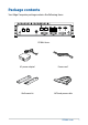
Package contents Your Edge Computer package contains the following items: PE200U Series AC power adapter* Power cord* Wall mount kit SATA and power cable PE200U Series 7
NOTE: • *The bundled power adapter may vary by model and territories. • Some bundled accessories may vary with different models. For details on these accessories, refer to their respective user manuals. • The device illustration is for reference only. Actual product specifications may vary with models.
1 Getting to know your Edge Computer
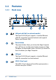
1.1 Features 1.1.1 Front view LAN port with PoE (on selected models) The 8-pin RJ-45 LAN port supports a standard Ethernet cable for connection to a local network, and supports Power over Ethernet (PoE). Power button The power button allows you to turn the Edge Computer on or off. You can use the power button to put your Edge Computer to sleep mode or press it for four (4) seconds to force shutdown your Edge Computer.
HDMI port The HDMI (High Definition Multimedia Interface) port supports a Full-HD device such as an LCD TV or monitor to allow viewing on a larger external display. Dual-mode DisplayPort This port allows you to connect your Edge Computer to an external display, and supports DVI or HDMI adpaters. Antenna hole The antenna hole allows you to connect a wireless antenna to enhance wireless signal reception.
1.1.2 Rear view Serial (COM) connector (on selected models) The 9-pin RS-232 serial (COM) connector allows you to connect devices that have serial ports such as bar code scanner, modem, or printers. USB 2.0 port (on selected models) The USB (Universal Serial Bus) port is compatible with USB 2.0 or USB 1.1 devices such as keyboards, pointing devices, flash disk drives, external HDDs, speakers, cameras and printers.
Antenna hole The antenna hole allows you to connect a wireless antenna to enhance wireless signal reception. Headphone jack This port allows you to connect amplified speakers or headphones.
1.2 Motherboard Overview 1.2.1 Motherboard layout The PE200U Series features a motherboard with a 3.5” dimension (146mm x 105mm).
Layout contents Page 1. M.2 Wi-Fi slot 24 2. Nano SIM Card slot 24 3. Mini PCIe/mSATA slot 22 4. DIMM slot 16 5. Low Pin Count connector 26 6. Battery connector 26 7. LVDS connector (on selected models) 25 8. Back Light Inverter Power connector (on selected models) 33 9. EDP Signal connector (on selected models) 27 10. LVDS Panel Power Selection jumper (on selected models) 18 11. Back Light Power Selection jumper (on selected models) 18 12.
1.2.2 System memory The motherboard comes with a Small Outline Dual Inline Memory Module (SODIMM) slot designed for DDR4 (Double Data Rate 4) memory modules.
1.2.3 1. Onboard jumpers Clear RTC RAM jumper The Clear RTC RAM jumper allows you to clear the Real Time Clock (RTC) RAM in the CMOS, which contains the date, time, system passwords, and system setup parameters. To erase the RTC RAM: 1. Turn OFF the computer and unplug the power cord. 2. Short-circuit pin 1-2 with a metal object or jumper cap for about 5-10 seconds. 3. Plug the power cord and turn ON the computer. 4.
2. LVDS Panel Power Selection jumper (on selected models) The LVDS Panel Power jumper allows you to select the voltage for the LVDS panel. 3. Back Light Power Selection jumper (on selected models) The Back Light Power Selection jumper allow you to select the voltage for the LVDS back light module.
4. Back Light Power Enable jumper (on selected models) The Back Light Power Enable jumper allows you to configure the power setting for the panel. 5. HW WDT Enable jumper A watchdog timer is an electronic timer that is used to detect and recover from computer malfunctions. The HW WDT (watchdog timer) Enable jumper allows the HW watchdog resets the system automatically even when the system crashes. NOTE: The default setting for this jumper is set to HW WDT enabled with a jumper cap attached.
6. AT/ATX Mode Configuration jumper The AT/ATX Mode Configuration jumper allows you to switch between AT or ATX modes. The default setting for this jumper is set to ATX mode with a jumper cap attached, to switch to AT mode, remove the jumper cap. 7. Mini PCIe/mSATA configuration jumper The Mini PCIe/mSATA configuration jumper allows you to select between Mini PCIe mode or mSATA mode. Set to pins 1-2 for mSATA mode, or set to pins 2-3 for Mini PCIe mode.
1.2.4 1. Internal connectors SATA 6Gb/s & SATA Power connector The SATA 6Gb/s and SATA Power connectors allow you to connect SATA devices such as optical disc drives and hard disk drives via a SATA cable and power cable. Connector type Wafer HD 4P, 2.0mm pitch NOTE: Ensure to use the bundled cable when connecting a storage device to this connector.
2. Mini PCIe/mSATA slot The Mini PCIe/mSATA slot allows you to install a Mini PCIe or mSATA peripheral device. NOTE: • The Mini PCIe / mSATA peripheral device is purchased separately. • The mSATA shares the same slot with a full-length Mini PCIe.
3. Micro SD Card slot The Micro SD Card slot allows you to install a Micro SD card. NOTE: The Micro SD card is purchased separately. 4. M.2 slot The M.2 slot allows you to install 2242 M.2 devices such as 2242 M.2 SSD modules. NOTE: • The M.2 SSD module is purchased separately. • This motherboard supports 2242 PCIE SSD devices only.
5. M.2 Wi-Fi slot The M.2 Wi-Fi slot allows you to install an M.2 Wi-Fi module (E-key, type 2230). NOTE: The M.2 Wi-Fi module is purchased separately. 6. Nano SIM Card slot The Nano SIM Card slot allows you to install a Nano SIM card. NOTE: The Nano SIM card is purchased separately.
7. LVDS connector (on selected models) The LVDS connector allows you to connect a LCD monitor that supports a Low-voltage Differential Signaling (LVDS) interface. Connector type 8. WAFER HD 2X15P 1.25MM pitch Power button connector The Power Button connector allows you to connect an external power button.
9. Low Pin Count connector The Low Pin Count connector allows you to connect a low pin count (LPC) debug card that offers a faster, more efficient motherboard troubleshooting solution. When connected to a debug card, users can view error and debugging codes on the card and get a better idea of initialization and recovery processes. Connector type BOX header 2x5p, K10, 2.0mm pitch 10. Battery connector The Battery connector allows you to connect the lithium CMOS battery.
11. EDP Signal connector (on selected models) The EDP Signal connector allows you to connect an internal embedded DisplayPort. Connector type WtoB CON 40P 0.
12. System Management Bus connector The System Management Bus (SMBus) connector allows you to connect SMBus devices. This connector is generally used for communication with the system and power management-related tasks. Connector type Header 1x4p, 2.0mm pitch 13. GPIO connector The GPIO connector allows you to connect a general purpose input/ output module which allows you to customize the digital signal input/ output. Connector type 28 PE200U Series BOX header 2x5p, K9, 2.
14. I2C connector The I2C (Inter-Integrated Circuit)connector allows you to connect an I2C compatible IoT security module. Connector type Header 2x3p, K6, 2.0mm pitch 15. SPI TPM connector The SPI TPM connector supports a Trusted Platform Module (TPM) system, which can securely store keys, digital certificates, passwords, and data. A TPM system also helps enhance network security, protects digital identities, and ensures platform integrity. Connector type Header 2x7p,K14, 2.
16. Serial Port connector The Serial (COM) Port connector allows you to connect a serial port module. Connect the serial port module cable to this connector, then install the module to a slot opening on the system chassis. Connector type BOX header 2x5p, K10, 2.0mm pitch NOTE: • The serial port module is purchased separately. • COM1 and COM2 support RS-232/422/485. • COM 3, COM4, COM5, and COM6 support RS-232.
17. USB 2.0 connector The USB 2.0 connector allows you to connect a USB module for additional USB 2.0 ports. The USB 2.0 connector provides data transfer speeds of up to 480 MB/s connection speed. Connector type BOX header 2x5p, K9, 2.0mm pitch WARNING! DO NOT connect a 1394 cable to the USB connectors. Doing so will damage the motherboard! NOTE: The USB 2.0 module is purchased separately.
18. Chassis Intrusion connector The Chassis Intrusion connector allows you to connect a intrusion sensor or microswitch for the chassis intrusion detection feature. When you remove any chassis component, the sensor or microswitch triggers and sends a high level signal and records a chassis intrusion event. NOTE: By default, a jumper cap that disables the intrusion detection feature is installed on the connector to prevent accidental triggers.
19. Back Light Inverter Power connector (on selected models) The Back Light Inverter Power connector is for the panel back light module power input. Connector type WAFER 6P 2.0mm pitch NATURAL S/T 20. DC-in 4-Pin Power connector The DC-in 4-pin Power connector is for DC power input. Using a compatible power cable and power board, you may connect a suitable power supply with DC -in jacks.
21. Fan connector (on selected models) The Fan connector allows you to connect a fan to cool the system. Connector type WtoB CON 4P,1.25mm,S/T WARNING! • DO NOT forget to connect the fan cable to the fan connector. Insufficient air flow inside the system may damage the motherboard components. These are not jumpers! Do not place jumper caps on the fan connectors! • Ensure the cable is fully inserted into the connector.
22. System Panel connector The System Panel connector supports several chassis-mounted functions. Connector type BOX header 2x5p 2.0mm pitch • System Power LED connector (PLED) The 2-pin connector allow you to connect the System Power LED. The System Power LED lights up when the system is connected to a power source, or when you turn on the system power, and blinks when the system is in sleep mode.
23. Line Out / Mic connector The Line Out / Mic connector is for a line out /microphone module that supports HD Audio. Connect one end of the line Out / mic module cable to this connector. Connector type BOX header 2x5p, K8, 2.0mm pitch NOTE: We recommend that you connect a high-definition line out / mic module to this connector to avail of the motherboard’s highdefinition audio capability.
2 Using your Edge Computer
2.1 Getting started 2.1.1 Connect the AC power adapter to your Edge Computer To connect the AC power adapter to your Edge Computer: A. Connect the power cord to the AC power adapter. B. Connect the DC power connector into your Edge Computer’s power (DC) input. C. Plug the AC power adapter into a 100V~240V power source. NOTE: The power adapter may vary in appearance, depending on models and your region.
IMPORTANT! • We strongly recommend that you use only the AC power adapter and cable that came with your Edge Computer. • We strongly recommend that you use a grounded wall socket while using your Edge Computer. • The socket outlet must be easily accessible and near your Edge Computer. • To disconnect your Edge Computer from its main power supply, unplug your Edge Computer from the power socket.
2.1.2 Connect a display panel to your Edge Computer You can connect a display panel or projector to your Edge Computer that has the following connectors: • HDMI connector • DisplayPort To connect a display panel to your Edge Computer: Connect one end of an HDMI, or a DisplayPort cable to an external display, and the other end of the cable to your Edge Computer’s HDMI port, or DisplayPort.
Connect display via DisplayPort PE200U Series 41
2.1.3 Connect the USB cable from keyboard or mouse You can connect generally any USB keyboard and mouse to your Edge Computer. You can also connect a USB dongle for a wireless keyboard and mouse set. To connect a keyboard and mouse to your Edge Computer: Connect the USB cable from your keyboard and mouse to any of the USB ports of your Edge Computer. NOTE: • The keyboard varies with country or region. • The keyboard and mouse are purchased separately.
2.1.4 Turn on your Edge Computer Press the power button to turn on your Edge Computer.
2.2 Turning your Edge Computer off If your Edge Computer is unresponsive, press and hold the power button for at least four (4) seconds until your Edge Computer turns off. 2.3 Putting your Edge Computer to sleep To put your Edge Computer on Sleep mode, press the Power button once. 2.4 Entering the BIOS Setup BIOS (Basic Input and Output System) stores system hardware settings that are needed for system startup in the Edge Computer.
2.4.1 Load default BIOS settings To load the default values for each of the parameters in your BIOS: • Enter the BIOS by pressing or on the POST screen. NOTE: POST (Power-On Self Test) is a series of software controlled diagnostic tests that run when you turn on your Edge Computer. • • • Navigate to the Exit menu. Select the Load Optimized Defaults option, or you may press . Select OK to load the default BIOS values.
PE200U Series
Upgrading your Edge Computer 3
IMPORTANT! • Ensure that your hands are dry before proceeding with the rest of the installation process. Before installing any of the features in this guide, use a grounded wrist strap or touch a safely grounded object or metal object to avoid damaging them due to static electricity. • Turn off the power of your Edge Computer, and allow it to cool for at least 10 minutes before performing any installation/ uninstallation process. NOTE: The illustrations in this section are for reference only.
3.2 Replacing the bottom cover 1. Align the bottom cover with the screw holes, then replace the bottom cover onto the Edge Computer. 2. Secure the bottom cover using the four (4) screws removed previously. 3. Replace the four (4) rubber feet screws removed previously.
3.3 Installing memory modules Your Edge Computer comes with a SO-DIMM memory slot that allow you to install a DDR4 SO-DIMM. Align and insert the memory module into the slot (A) and press it down (B) until it is securely seated in place.
3.4 Installing 2.5” storage device 1. Prepare your 2.5” storage device, then align it with the storage bay on the bottom cover of your Edge Computer. 2. Connect the storage device cable to the storage device. 3. Insert your storage device into the storage bay. 4. Secure the storage device to the storage bay using four (4) screws. IMPORTANT! This device only supports 7mm 2.5” HDD or SSD.
5. Connect the storage device cable to the SATA6G and SATA_PWR connectors on the motherboard. 6. Replace the bottom cover, then secure the bottom cover using the four (4) screws removed previously. 7. Replace the four (4) rubber feet screws removed previously.
3.5 Installing the Mini PCIe or mSATA card Your Edge Computer comes with a Mini PCIe/mSATA slot that allow you to install a Mini PCIe or mSATA peripheral card. Align and insert the Mini PCIe or mSATA card into the slot (A) and press it down and secure it in place using two (2) screws.
3.6 Installing a nano SIM card 1. (optional) Remove the mPCIe or mSATA card if there is a mPCIe or mSATA card installed by removing the two (2) screws securing the mPCIe or mSATA card first, then removing the mPCIe or mSATA card. 2. Push the nano SIM cover towards the front of your Edge Computer. 3. Lift the nano SIM cover. 4. Place the nano SIM into the nano SIM slot. 5. Replace the nano SIM cover. 6. Push the nano SIM cover towards the rear of your Edge Computer to secure the nano SIM card.
3.7 Installing an SD card 1. Remove the five (5) screws on the rear cover, then slightly pull the rear cover outwards, but do not remove it completely. 2. Insert your SD card into the SD card slot. Ensure that the SD card is pushed all the way into the SD card slot.
3. Once your SD card is properly installed into the SD card slot, replace the rear cover and secure it using the five (5) screws removed previously.
3.8 Installing the wireless card 1. Remove the M.2 stand screw. 2. Align and insert the wireless card into its slot inside the Edge Computer, then gently push down the wireless card on top of the screw hole and fasten it using the previously removed stand screw. 3. (optional) Connect the antennas to your wireless card. NOTE: • Please refer to the Installing the antennas section for more information on installing the antennas.
3.9 Installing an M.2 SSD 1. (optional) Replace the stand screw if it has been removed. 2. Align and insert the M.2 SSD into its slot inside the Edge Computer, then gently push down the M.2 SSD on top of the stand screw hole and fasten it using a screw.
3.10 Installing the antennas (optional) You may install antennas to the four (4) antenna holes located on the front and rear panels. The installed antennas can be connected to a WWAN card installed in the Mini PCIe/mSATA slot, or to a wireless card installed in the M.2 Wi-Fi slot. 1. Remove the rubber caps from the antenna hole. 2. Prepare the RF connector and cable. 3. Insert the antenna jack end of the RF connector and cable into the antenna hole from within the chassis outwards. 4.
3.11 Installing the USB 2.0 module (on selected models) 1. Align the bundled USB 2.0 module with the USB 2.0 port holes and screw holes on the rear panel. 2. Secure the USB 2.0 module to the rear panel using two (2) bundled hex bolts and hex nuts. 3. Connect the USB 2.0 module connector to the USB 2.0 connector on the motherboard. NOTE: Please refer to the Motherboard layout section for the location of the USB 2.0 connectors. 4. To install another USB 2.0 module, please repeat steps 1-3.
3.12 Installing the Serial port module (on selected models) 1. Align the bundled Serial port module with the Serial port holes and screw holes on the rear panel. 2. Secure the Serial port module to the rear panel using two (2) bundled hex screws. 3. Connect the Serial port module connector to the Serial port connector on the motherboard. NOTE: Please refer to the Motherboard layout section for the location of the Serial port connectors. 4.
3.13 Installing the PoE LAN module (on selected models) NOTE: The PoE LAN module supports up to 15W per port for powering IEEE802.3af. 1. Connect the CN1 and CN2 connectors on the PoE LAN module’s daughter board to the CN1 and CN2 connectors on the PoE LAN module’s motherboard using the two (2) bundled LAN signal cables.
2. Connect the power connector on the daughter board to the power connector on the power board. 3. Secure the motherboard and daughter board using the bundled screws.
3.14 Installing the VESA mount (optional) You may install a VESA mount to your Edge Computer which allows you to install your Edge Computer to a VESA mount-compatible device. 1. Place your Edge Computer upside down on a flat and stable surface. 2. Attach the bundled two (2) 12mm screws into the screw holes at the bottom of your Edge Computer. 3. Remove the screw hole covers at the back of your VESA mountcompatible device, if any.
4. With the arrow on the VESA mounting plate pointing upward, align its screw holes to the screw holes of the VESA mount-compatible device. 5. Secure the VESA mounting plate to the VESA mount-compatible device using the bundled screws. WARNING! Do not overtighten the screws as it may cause damage to your VESA mount-compatible device. 6.
3.15 Installing the wall mount 1. Remove the four (4) rubber feet screws. 2. Align the wall mount with the rubber feet screw holes (A), then remove the rubber feet from the rubber feet screws (B) and secure the wall mount to your Edge Computer using the rubber feet screws (C).
Using the software 4
4.1 Installing IEC Vision Your Edge Computer can support the Intelligent Edge Console (IEC)Vision software. Download IEC Vision by visiting https://www.asus.com/AIoT-Industrial-Solutions/PE200U/HelpDesk_ Download/ To install IEC Vision, please follow the steps below: 1. Click on IEC Vision.msi, located on the desktop, to execute the installation wizard. 2. Click on Next.
3. Read through the License Agreement, then check the I accept the terms in the License Agreement box and click on Next. 4. Click on Next to install to the default folder destination, or click on Browse to select a different folder then click on Next.
5. Click on Install to begin the installation process. 6. Wait for the installation process to finish then click on Finish to complete the installation.
4.2 IEC Vision overview IEC Vision provides you with a GDPR compliant remote monitoring and control solution and supports USB cameras and PoE IP cameras. 4.2.1 Demographic Mode Camera select and settings: Select a camera to monitor. You may also add, edit, or delete an IP camera, or re-name your connected USB cameras or IP cameras. Widget settings: Enable or disable the Summary, Age or Gender widgets, or filter the data displayed on enabled widgets by day, week, or month.
Summary widget: Displays the total amount of people detected per hour of the day, per day of the week, or day of the month. Camera information: Displays camera type and resolution of the current camera being monitored. Age widget: Displays a bar graph of the amount of different age groups detected. Export data: Export the data collected on IEC Vision to an Excel file. Reset: Reset the data of the Total overview window. Total overview: Displays the total amount of gender, age and people count.
4.2.2 Dashboard Data filter: Select a time range to filter the data displayed on the dashboard. Summary: Displays the amount of male and female identified on a line graph and the total amount of people. The data may vary between hour of the day, day of the week, or day of the month according to the selected time range filter. Age Distribution: Displays a line graph of the amount of different age groups detected.
4.3 Configuring the camera IEC Vision allows you to easily add PoE IP cameras or use USB cameras. 4.3.1 1. Configuring a USB camera Connect a USB camera to an available USB port on your Edge Computer. NOTE: For more information on the location of the USB ports on your Edge Computer, please refer to the Features section of this manual. 2. Click on the Camera select and settings drop down menu located at the top right of the main screen. 3. Click on Camera Settings.
4. Click on the USB Camera tab. You may edit the name of your connected USB camera(s) here by clicking on next to the USB camera you wish to rename.
4.3.2 Configuring a PoE IP camera 1. Click on the Camera select and settings drop down menu located at the top right of the main screen. 2. Click on the IP Camera tab, then click on Add new camera to add a new IP camera.
3. Enter a camera name, and select a protocol and URL for the PoE IP camera you wish to link to, then click on ADD CAMERA to add the IP camera.
PE200U Series
Appendix
Safety information Your Edge Computer is designed and tested to meet the latest standards of safety for information technology equipment. However, to ensure your safety, it is important that you read the following safety instructions. Setting up your system • • • • • • • • • 80 Read and follow all instructions in the documentation before you operate your system. Do not use this product near water or a heated source. Set up the system on a stable surface.
Care during use • Do not walk on the power cord or allow anything to rest on it. • • Do not spill water or any other liquids on your system. When the system is turned off, a small amount of electrical current still flows. Always unplug the power cord from the power outlets before cleaning the system. If you encounter the following technical problems with the product, unplug the power cord and contact a qualified service technician or your retailer. – The power cord or plug is damaged.
Regulatory notices REACH Complying with the REACH (Registration, Evaluation, Authorization, and Restriction of Chemicals) regulatory framework, we publish the chemical substances in our products at ASUS REACH website at http://csr.asus.com/ english/REACH.htm ASUS Recycling/Takeback Services ASUS recycling and takeback programs come from our commitment to the highest standards for protecting our environment.
Federal Communications Commission Statement This device complies with Part 15 of the FCC Rules. Operation is subject to the following two conditions: • • This device may not cause harmful interference, and This device must accept any interference received including interference that may cause undesired operation. This equipment has been tested and found to comply with the limits for a Class A digital device, pursuant to part 15 of the FCC Rules.
ISED Radiation Exposure Statement for Canada This equipment complies with ISED radiation exposure limits set forth for an uncontrolled environment. To maintain compliance with ISED RF exposure compliance requirements, please avoid direct contact to the transmitting antenna during transmitting. End users must follow the specific operating instructions for satisfying RF exposure compliance.
Wireless Operation Channel for Different Domains N. America 2.412-2.462 GHz Ch01 through CH11 Japan 2.412-2.484 GHz Ch01 through Ch14 Europe ETSI 2.412-2.472 GHz Ch01 through Ch13 Regional notice for Singapore Complies with IMDA Standards DB103778 This ASUS product complies with IMDA Standards. Regional notice for California WARNING! This product contains chemicals known to the State of California to cause cancer, and birth defects or other reproductive harm. Wash hands after handling.
ENERGY STAR complied product ENERGY STAR is a joint program of the U.S. Environmental Protection Agency and the U.S. Department of Energy helping us all save money and protect the environment through energy efficient products and practices. All ASUS products with the ENERGY STAR logo comply with the ENERGY STAR standard, and the power management feature is enabled by default. The monitor and computer are automatically set to sleep after 10 and 30 minutes of user inactivity.
ASUS contact information ASUSTeK COMPUTER INC. Address Telephone Fax Web site 4F, No. 150, Li-Te Road, Peitou, Taipei 112, Taiwan +886-2-2894-3447 +886-2-2890-7798 www.asus.com Technical Support Telephone +86-21-38429911 Fax +86-21-5866-8722, ext. 9101# Online support https://www.asus.com/support/Product/ContactUs/Services/ questionform/?lang=en ASUS COMPUTER INTERNATIONAL (America) Address Telephone Fax Web site Technical Support Support fax Telephone Online support 48720 Kato Rd.
PE200U Series