Motherboard ROG RAMPAGE VI EXTREME
E13932 Revised Edition V2 February 2018 Copyright© 2018 ASUSTeK COMPUTER INC. All Rights Reserved. No part of this manual, including the products and software described in it, may be reproduced, transmitted, transcribed, stored in a retrieval system, or translated into any language in any form or by any means, except documentation kept by the purchaser for backup purposes, without the express written permission of ASUSTeK COMPUTER INC. (“ASUS”).
Contents Safety information....................................................................................................... vi About this guide......................................................................................................... vii ROG RAMPAGE VI EXTREME specifications summary.......................................... ix Package contents....................................................................................................... xv Installation tools and components.....
Chapter 3: Knowing BIOS............................................................................................. 3-1 3.2 BIOS setup program................................................................................... 3-2 3.2.1 Advanced Mode........................................................................... 3-3 3.2.2 EZ Mode...................................................................................... 3-6 3.2.3 Q-Fan Control...................................................
Chapter 4: 4.1 4.2 RAID Support RAID configurations................................................................................... 4-1 4.1.1 RAID definitions........................................................................... 4-1 4.1.2 Installing storage devices............................................................. 4-2 4.1.3 Intel® Rapid Storage Technology in UEFI BIOS........................... 4-2 4.1.4 Intel® Virtual Raid on CPU in UEFI BIOS....................................
Safety information Electrical safety • To prevent electrical shock hazard, disconnect the power cable from the electrical outlet before relocating the system. • When adding or removing devices to or from the system, ensure that the power cables for the devices are unplugged before the signal cables are connected. If possible, disconnect all power cables from the existing system before you add a device.
About this guide This user guide contains the information you need when installing and configuring the motherboard. How this guide is organized This guide contains the following parts: 1. Chapter 1: Product Introduction This chapter describes the features of the motherboard and the new technology it supports. It includes description of the switches, jumpers, and connectors on the motherboard. 2.
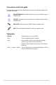
Conventions used in this guide To ensure that you perform certain tasks properly, take note of the following symbols used throughout this manual. DANGER/WARNING: Information to prevent injury to yourself when trying to complete a task. CAUTION: Information to prevent damage to the components when trying to complete a task. IMPORTANT: Instructions that you MUST follow to complete a task. NOTE: Tips and additional information to help you complete a task.
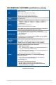
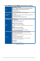
ROG RAMPAGE VI EXTREME specifications summary Intel® Socket 2066 for Intel® Core™ X-Series Processor 79xx, 78xx Series Supports 14nm CPU CPU Supports Intel® Virtual RAID on CPU (VROC)* Supports Intel® Turbo Boost Max Technology 3.0* * Support of these features depends on the CPU types. Chipset Memory Intel® X299 Chipset 8 x DIMM, max. 128GB, DDR4 4200+(O.C)* / 4000(O.C.)* / 3866(O.C.)* / 3600(O.C.)* / 3333(O.C.)* / 3300(O.C.)* / 3200(O.C.)* / 3000(O.C.)* / 2800(O.C.)* / 2666(O.C.)* / 2400(O.C.
ROG RAMPAGE VI EXTREME specifications summary Aquantia AQC-107 10G LAN LAN Intel® I219-V Gigabit LAN- Dual interconnect between the integrated Media Access Controller (MAC) and physical layer (PHY) Anti-surge LANGuard ROG GameFirst Technology Wi-Fi 802.11ad(WiGig) supports frequency band 60GHz* Wireless Data Network Up to 4.6Gbps 2x2 MU-MIMO 802.11 a/b/g/n/ac supports dual frequency band 2.4/5 GHz Up to 867Mbps transfer speed * 802.11ad(WiGig) is only available in certified countries.
ROG RAMPAGE VI EXTREME specifications summary 1 x 4-pin VROC key 1 x USB 3.1 Gen 2 front panel connector 2 x USB 3.1 Gen 1 connectors support additional 4 USB 3.1 Gen 1 ports 1 x USB connector supports 2 USB 2.0 ports [one connector via ROG_EXT header] 6 x SATA 6Gb/s connectors 1 x U.2 port 1 x M.2 PCIe 3.0 x4 Socket 3 with M Key, type 2242/2260/2280 (supports PCIe3.
ROG RAMPAGE VI EXTREME specifications summary 1 x Clear CMOS button 1 x BIOS Flashback button 1 x ASUS Wi-Fi GO! module (1x1 802.11 ad Wi-Fi + 2x2 MU-MIMO 802.11 a/b/g/n/ac and Bluetooth v4.1) Back Panel I/O Ports 1 x Aquantia AQC-107 10G LAN 1 x Anti-surge LAN (RJ45) port 2 x USB 3.1 Gen 2 ports (1 x Type-C [black] and 1 x Type-A [red]) 8 x USB 3.
ROG RAMPAGE VI EXTREME specifications summary ROG DIMM.2 module Extreme Engine Digi+ - MicroFine Alloy Choke - NexFET MOSFET - 10K Black Metallic Capacitors OC Zone - ReTry button - Safe Boot button - LN2 Mode header - Slow Mode switch - Start button - Reset button - ProbeIt - PCIe x16 lane switches ROG Exclusive Features ROG CloneDrive ROG RAMCache II ROG RAMDisk AURA KeyBot II - One-click overclocking - X.M.P.
ROG RAMPAGE VI EXTREME specifications summary BIOS Features 2 x 128 Mb Flash ROM, UEFI AMI BIOS, PnP, WfM2.0, SM BIOS 3.0, ACPI 6.0, Multi-language BIOS, ASUS EZ Flash 3, CrashFree BIOS 3, F11 EZ Tuning Wizard, F6 Qfan Control, F3 My Favorites, Last Modified log, F12 PrintScreen, and ASUS DRAM SPD (Serial Presence Detect) memory information. Manageability WfM 2.
Package contents Check your motherboard package for the following items. Motherboard 1 x ROG RAMPAGE VI EXTREME motherboard 3 x 2-in-1 SATA 6Gb/s cables 1 x 3-in-1 thermistor cable 1 x Cable for Fan Extension card Cables 1 x Extension cable for addressable RGB strip 1 x Extension cable for RGB strip (80cm) 1 x ASUS 2x2 dual band Wi-Fi antenna (Wi-Fi 802.11a/b/g/n/ ac compliant) 1 x ASUS Wi-Fi 802.
Installation tools and components Intel® LGA 2066 CPU Intel® LGA 2066 compatible CPU Fan PC chassis SATA hard disk drive Phillips (cross) screwdriver DIMM 1 bag of screws Power supply unit SATA optical disc drive (optional) Graphics card M.2 SSD module (optional) The tools and components in the table above are not included in the motherboard package.
Product Introduction Product Introduction 1.1 Motherboard overview 1.1.1 Before you proceed 1 Chapter 1 Chapter 1: Take note of the following precautions before you install motherboard components or change any motherboard settings. • Unplug the power cord from the wall socket before touching any component. • Before handling components, use a grounded wrist strap or touch a safely grounded object or a metal object, such as the power supply case, to avoid damaging them due to static electricity.
1.1.2 Motherboard layout Chapter 1 Refer to 1.1.9 Internal connectors and 2.3.1 Rear I/O connection for more information about rear panel connectors and internal connectors.
Layout contents ROG RAMPAGE VI EXTREME Page 1-5 1-4 1-23 Chapter 1 Connectors/Jumpers/Buttons and switches/Slots 1. DDR4 DIMM slots 2. LGA2066 CPU socket 3. ATX power connectors (24-pin EATXPWR; 8-pin EATX12V1; 4-pin EATX12V2; 4-pin EZ_PLUG)) 4. DIMM.2 slot (DIMM.2_SLOT) 5. PCIe x16 Lane switch (PCIEX16_SW) 6. Fan and pump connectors (4-pin CPU_FAN; 4-pin CPU_OPT; 4-pin H_ AMP_FAN; 4-pin W_PUMP+1; 4-pin W_PUMP+2; 5-pin EXT_FAN; 4-pin CHA_FAN1-3) 7. Slow Mode switch (SLOW_MODE) 8.
1.1.3 Central Processing Unit (CPU) The motherboard comes with a surface mount LGA2066 socket designed for the Intel® Core™ X-series Processor 79xx, 78xx Series. Chapter 1 1-4 • Ensure that all power cables are unplugged before installing the CPU. • Upon purchase of the motherboard, ensure that the PnP cap is on the socket and the socket contacts are not bent. Contact your retailer immediately if the PnP cap is missing, or if you see any damage to the PnP cap/socket contacts/motherboard components.
1.1.4 System memory Chapter 1 The motherboard comes with eight DDR4 (Double Data Rate 4) Dual Inline Memory Modules (DIMM) slots. A DDR4 module is notched differently from a DDR, DDR2, or DDR3 module. DO NOT install a DDR, DDR2, or DDR3 memory module to the DDR4 slot.
Memory configurations You may install 2 GB, 4 GB, 8 GB and 16 GB unbuffered and non‑ECC DDR4 DIMMs into the DIMM sockets. Chapter 1 For Intel® Core™ X-Series Processor 78xx, 79xx Series, you may install varying memory sizes in Channel A, Channel B, Channel C, and Channel D. The system maps the total size of the lower-sized channel for the quad-channel configuration. Any excess memory from the higher-sized channel is then mapped for single-channel operation.
1.1.5 Expansion slots Chapter 1 Unplug the power cord before adding or removing expansion cards. Failure to do so may cause you physical injury and damage motherboard components. Slot No.
44-Lane CPUs PCI Express 3.0 operating mode Chapter 1 VGA / PCIe configuration Single VGA / PCIe card Dual VGA / PCIe cards Triple VGA / PCIe cards* Triple VGA / Quad VGA / PCIe cards PCIe cards PCIex16/x8_1 x16 x16 x16 x16 x16 PCIex8_2 x8 N/A N/A x8 x8 PCIex16/x8_3 x8 x16 x16 x8 x8 PCIex8_4 x4 x4 x8 x8 x8 * Please use the bundled 4-way SLI bridge to enable this configuration. ® 28-Lane CPUs PCI Express 3.
1.1.6 Onboard buttons and switches 1. Chapter 1 Onboard buttons and switches allow you to fine-tune performance when working on a bare or open-case system. This is ideal for overclockers and gamers who continually change settings to enhance system performance. Power-on button The motherboard comes with a power-on button that allows you to power up or wake up the system.
3. MemOK! button Chapter 1 Installing DIMMs that are not compatible with the motherboard may cause system boot failure. If the system fails to boot during POST stage and the DRAM_LED lights continuously, press the MemOK! button until the DRAM_LED starts blinking. System will begin automatic memory compatibility tuning and reboot for successful boot. 1-10 • Refer to section 1.1.8 Onboard LEDs for the exact location of the DRAM_LED.
4. Safe Boot button (SAFE_BOOT) 5. Chapter 1 The Safe Boot button can be pressed anytime to force the system to reboot into the BIOS safe mode. This button temporarily applies safe settings to the BIOS while retaining any overclocked settings allowing you to modify the settings causing boot failure. Use this button when overclocking or tweaking the settings of your system.
6. BIOS Switch button (BIOS_SWITCH) The motherboard comes with two BIOS chips. Press the BIOS button to switch BIOS and load different BIOS settings. The nearby BIOS_LEDs indicate the currently selected BIOS. Chapter 1 7. Pause switch (PAUSE) The pause switch allows you to freeze the cooling system at a hardware level, thus allowing you to adjust your system settings under heavy overclocking.
8. Slow Mode switch (SLOW_MODE) 9. Chapter 1 Slow Mode Switch is employed during LN2 benching. The system may crash due to the CPU being unstable when using extreme overclocking, enabling slow mode will decrease the processor frequency and stabilize the system, allowing overclockers to keep track of their overclocking data. RSVD switch (RSVD_1-2) This switch is reserved for ASUS-authorized technicians only. Ensure to set this switch to disabled, enabling this switch may cause system failure.
10. PCIe x16 Lane switch (PCIEX16_SW) These slide switches allows you to enable and disable the corresponding PCIe x16 slots. When one of the installed PCIe x16 cards is out of order, you can use the slide switch to find the faulty one without removing the cards.
1.1.7 1. Jumpers LN2 Mode jumper (3-pin LN2_MODE) ROG RAMPAGE VI EXTREME Chapter 1 With LN2 mode activated, the ROG motherboard is optimized to remedy the cold-boot bug during POST and help the system boot successfully.
1.1.8 1. Onboard LEDs Q LEDs (CPU, DRAM, VGA, BOOT) Chapter 1 Q LEDs check key components (CPU, DRAM, VGA card, and booting devices) in sequence during motherboard booting process. If an error is found, the corresponding LED remains lit until the problem is solved. This user-friendly design provides an intuitive way to locate the root problem within seconds. The Q LEDs provide the most probable cause of an error code as a starting point for troubleshooting. The actual cause may vary from case to case.
3. DIMM LED (DIMM_A_LED; DIMM_B_LED; DIMM_C_LED; DIMM_D_LED) Chapter 1 The DIMM LED indicates when the corresponding memory channel is enabled. 4. Hard Disk LED (HD_LED) The Hard Disk LED is designed to indicate the hard disk activity. It blinks when data is being written into or read from the hard disk drive. The LED does not light up when there is no hard disk drive connected to the motherboard or when the hard disk drive does not function.
1.1.9 Internal connectors 1. Intel® Serial ATA 6 Gb/s connectors (7-pin SATA6G_12; SATA 6G_34; SATA 6G_56) Chapter 1 These connectors connect to Serial ATA 6 Gb/s hard disk drives via Serial ATA 6 Gb/s signal cables. If you installed Serial ATA hard disk drives, you can create a RAID 0, 1, 5, and 10 configuration with the Intel® Rapid Storage Technology through the onboard Intel® X299 chipset. 1-18 • These connectors are set to [AHCI Mode] by default.
2. Front panel audio connector (10-1 pin AAFP) Chapter 1 This connector is for a chassis-mounted front panel audio I/O module that supports HD Audio. Connect one end of the front panel audio I/O module cable to this connector. We recommend that you connect a high-definition front panel audio module to this connector to avail of the motherboard’s high-definition audio capability. 3. USB 3.1 Gen 2 front panel connector (U31G2_E2) This connector allows you to connect a USB 3.
4. USB 3.1 Gen 1 connector (20-1 pin U31G1_E12; 20-1 pin U31G1_E34) Chapter 1 These connectors allow you to connect a USB 3.1 Gen 1 module for additional USB 3.1 Gen 1 front or rear panel ports. With an installed USB 3.1 Gen 1 module, you can enjoy all the benefits of USB 3.1 Gen 1 including faster data transfer speeds of up to 5 Gb/s, faster charging time for USB-chargeable devices, optimized power efficiency, and backward compatibility with USB 2.0. The USB 3.1 Gen 1 module is purchased separately.
5. USB 2.0 connector (10-1 pin USB1314) 6. Chapter 1 This connector is for USB 2.0 ports. Connect the USB module cable to this connector, then install the module to a slot opening at the back of the system chassis. This USB connector complies with USB 2.0 specification that supports up to 480 Mb/s connection speed. Thermal sensor connectors (2-pin T_SENSOR1-2) These connectors are for the thermistor cables that monitor the temperature of the devices and the critical components inside the motherboard.
7. Fan and pump connectors (4-pin CPU_FAN; 4-pin CPU_OPT; 4-pin H_AMP_FAN; 4-pin W_PUMP+1; 4-pin W_PUMP+2; 5-pin EXT_FAN; 4-pin CHA_FAN1-3) Connect the fan cables to the fan connectors on the motherboard, ensuring that the black wire of each cable matches the ground pin of the connector. Chapter 1 The EXT_FAN connector is only for the fan extension card. For more details on the fan extension card, please refer to the To install Fan Extension Card section in this guide.
8. ATX power connectors (24-pin EATXPWR; 8-pin EATX12V1; 4-pin EATX12V2; 4-pin EZ_PLUG) • DO NOT connect the 4-pin power plug only, the motherboard may overheat under heavy usage. • Ensure to connect the 8-pin power plug, or connect both the 8-pin and 4-pin power plugs. • For a fully configured system, we recommend that you use a power supply unit (PSU) that complies with ATX 12V Specification 2.0 (or later version) and provides a minimum power of 350 W.
9. System panel connectors (10-1 pin F_PANEL; 4-pin SPEAKER) This connector supports several chassis-mounted functions. Chapter 1 • System power LED (2-pin PLED) The 2-pin connector is for the system power LED. Connect the chassis power LED cable to this connector. The system power LED lights up when you turn on the system power, and blinks when the system is in sleep mode. • Hard disk drive activity LED (2-pin HDLED) This 2-pin connector is for the HDD Activity LED.
10. Thunderbolt header (5-pin TB_HEADER) Chapter 1 This connector is for the add-on Thunderbolt I/O card that supports Intel’s Thunderbolt Technology, allowing you to connect up to six Thunderbolt-enabled devices and a DisplayPort-enabled display in a daisy-chain configuration. The add-on Thunderbolt I/O card and Thunderbolt cables are purchased separately. 11. LED connector (13-pin LED_CON2) This connector is for connecting LED strips on your cover.
12. AURA RGB headers (4-pin RGB_HEADER1-2) These connectors are for RGB LED strips. Chapter 1 The RGB header supports 5050 RGB multi-color LED strips (12V/G/R/B), with a maximum power rating of 2A (12V), and no longer than 2 m. Before you install or remove any component, ensure that the ATX power supply is switched off or the power cord is detached from the power supply. Failure to do so may cause severe damage to the motherboard, peripherals, or components.
13. Addressable RGB header (4-1 pin ADD_HEADER) Chapter 1 This connector is for individually addressable RGB WS2812B LED strips or WS2812B based LED strips. The addressable RGB header supports WS2812B addressable RGB LED strips (5V/Data/ Ground), with a maximum power rating of 3A (5V) and a maximum of 60 LEDs. Before you install or remove any component, ensure that the ATX power supply is switched off or the power cord is detached from the power supply.
14. U.2 connector (U.2) This motherboard comes with a U.2 connector which supports PCIe 3.0 x4 NVM Express storage. Chapter 1 The U.2 connector shares bandwidth with the M.2_1 socket . Adjust the BIOS settings to use U.2 devices. 15. M.2 sockets (M.2_1(Socket 3)) This socket allows you to install an M.2 SSD module. • M.2_1 socket supports PCIe 3.0 x4 and SATA mode M Key design and type 2242 / 2260 / 2280 / 22110 PCIe and SATA storage devices.
16. DIMM.2 slot (DIMM.2_SLOT) Chapter 1 This socket allows you to install the bundled DIMM.2 card to connect M.2 SSD modules. • Before you install or remove the DIMM.2 card, ensure that the ATX power supply is switched off or the power cord is detached from the power supply. Failure to do so may cause severe damage to the motherboard or DIMM.2 card. • The DIMM.2 card is notched to fit in only one orientation. Ensure that the notch on your card is aligned correctly with the DIMM.
17. Water in, water out, and water flow connectors (2-pin W_IN; 2-pin W_OUT; 3-pin W_FLOW) Chapter 1 These connectors allow you to connect sensors to monitor the temperature and flow rate of your liquid cooling system. You can manually adjust the fans and water pump to optimize the thermal efficiency of your liquid cooling system. 18.
19. ROG extension connector (18-1 pin ROG_EXT) Chapter 1 This connector is for the OC Panel I/II. 20. • The OC Panel I/II is purchased separately. • Support for OC Panel I/II varies over different platforms. • Visit www.asus.com for more information about the devices and the latest compatibility list. TPM connector (14-1 pin TPM) This connector supports a Trusted Platform Module (TPM) system, which securely stores keys, digital certificates, passwords and data.
21. VROC_HW_KEY connector (4-pin VROC_HW_KEY) This connector allows you to connect a KEY module to enable CPU RAID functions with Intel® CPU RSTe. Chapter 1 22. • The KEY module is purchased separately. • Due to CPU behavior, CPU RAID functions with Intel® CPU RSTe only supports Intel® Core™ X-series Processor 79xx, 78xx Series, and Intel® SSD modules. OLED connector (9-pin OLED_HEADER) This connector is used to connect your LiveDash OLED panel.
1.1.10 ProbeIt The ROG ProbeIt allows you to detect your system’s current voltage and OC settings. Use a multimeter to measure the ProbeIt points even during overclocking. Chapter 1 See the illustration below to locate the respective ProbeIt points. Using ProbeIt You can connect the multimeter to the motherboard as shown on the following figure. The illustration above is for reference only, the actual motherboard layout and measure points may differ by model.
Chapter 1 1-34 Chapter 1: Product Introduction
Chapter 2: Basic Installation Basic Installation 2.1 Building your PC system 2 The diagrams in this section are for reference only. The motherboard layout may vary with models, but the installation steps are the same for all models. 2.1.1 CPU installation Chapter 2 Please note the order in opening/ closing the double latch. Follow the instructions printed on the metal sealing hatch or the illustrations shown below in this manual.
Triangle mark Triangle mark Chapter 2 2-2 Chapter 2: Basic Installation
2.1.2 CPU heatsink and fan assembly installation Apply the Thermal Interface Material to the CPU heatsink and CPU before you install the heatsink and fan, if necessary.
2.1.3 Motherboard installation Chapter 2 1. Place the motherboard into the chassis, ensuring that its rear I/O ports are aligned to the chassis’ rear I/O panel. 2. Place nine (9) screws into the holes indicated by circles to secure the motherboard to the chassis. DO NOT overtighten the screws! Doing so can damage the motherboard.
DIMM installation Chapter 2 2.1.
2.1.5 ATX power connection Chapter 2 OR 2-6 AND • DO NOT connect the 4-pin power plug only, the motherboard may overheat under heavy usage. • Ensure to connect the 8-pin power plug, or connect both the 8-pin and 4-pin power plugs.
2.1.
2.1.7 Front I/O connector To install ASUS Q-Connector To install USB 3.1 Gen 2 connector USB 3.1 Gen 2 Chapter 2 This connector will only fit in one orientation. Push the connector until it clicks into place. To install USB 3.1 Gen 1 connector To install USB 2.0 connector USB 3.1 Gen 1 USB 2.
2.1.
To install FAN EXTENSION CARD Chapter 2 The illustrations in this section are for reference only. The motherboard layout may vary with models, but the installation steps are the same for all models.
To install ThunderboltEX 3 card C USB 3.1 TYPE 3 THUNDERBOLT ort IN A MINI DisplayP Chapter 2 USB 3.1 TYPE C USB 3.1 TYPE 3 THUNDERBOLT USB 3.1 TYPE ort IN A MINI DisplayP The illustrations in this section are for reference only. The motherboard layout may vary with models, but the installation steps are the same for all models.
2.1.9 M.2 installation Chapter 2 Supported M.2 type varies per motherboard.
2.1.10 Fan bracket installation Chapter 2 To install the MOS FAN bracket When using high performance settings whilst overclocking, ensure to install the MOS FAN bracket for additional fan(s). Fans are purchased separately.
To install the DIMM.2 FAN mount 1 2 3 3 Chapter 2 4 5 5 2-14 • You may install up to two 50mm x 50mm fans or a single 100mm x 100 mm fan. • Fans are purchased separately.
2.1.11 Wi-Fi antenna installation Installing the ASUS 2x2 dual band W-Fi and ASUS Wi-Fi 802.11ad(WiGig) antenna Chapter 2 Connect the bundled ASUS 2x2 dual band Wi-Fi antenna connector to the top two Wi-Fi ports at the back of the chassis, then connect the Wi-Fi 802.11ad(WiGig) antenna to the bottom Wi-Fi port. ASUS 2x2 dual band W-Fi antenna ASUS Wi-Fi 802.11ad(WiGig) antenna • Ensure that the ASUS 2x2 dual band W-Fi and ASUS Wi-Fi 802.11ad(WiGig) antenna is securely installed to the Wi-Fi ports.
2.2 BIOS update utility USB BIOS Flashback USB BIOS Flashback allows you to easily update the BIOS without entering the existing BIOS or operating system. Simply insert a USB storage device to the USB port (the USB port hole marked in green on the I/O shield) then press the USB BIOS Flashback button for three seconds to automatically update the BIOS. To use USB BIOS Flashback: 1. Insert a USB storage device to the USB Flashback port. We recommend you to use a USB 2.
2.3 Motherboard rear and audio connections 2.3.1 Rear I/O connection 1. Clear CMOS button (CLR_CMOS). Press this button to clear the BIOS setup information only when the systems hangs due to overclocking. 2. Wi-Fi 802.11 a/b/g/n/ac/ad, Bluetooth V4.2 ports 3. USB 3.1 Gen 1 ports E5678 4. Aquantia AQC-107 10G LAN port 5. Intel® USB 3.1 Gen 1 ports 34 6. LAN (RJ-45) port* 7. USB BIOS Flashback button 8. Intel® USB 3.1 Gen 1 ports 56.
* LAN port LED indications Activity Link LED Speed LED Status Description Status Description Off No link Off Orange Linked Orange 100 Mbps connection Orange (Blinking) Data activity Orange (Blinking then steady) 10 Mbps connection Green ACT/LINK LED SPEED LED 1 Gbps connection Ready to wake up from S5 mode LAN port You can disable the LAN controllers in BIOS. Due to hardware design, the LAN1 port’s LEDs may continue to blink even when disabled.
2.3.
Connect to 4-channel Speakers Connect to 5.1-channel Speakers Chapter 2 Connect to 7.
2.4 Starting up for the first time 1. After making all the connections, replace the system case cover. 2. Ensure that all switches are off. 3. Connect the power cord to the power connector at the back of the system chassis. 4. Connect the power cord to a power outlet that is equipped with a surge protector. 5. Turn on the devices in the following order: a. b. External SCSI devices (starting with the last device on the chain) c.
Chapter 2 2-22 Chapter 2: Basic Installation
Chapter 3: BIOS Setup BIOS Setup 3.1 Knowing BIOS 3 The new ASUS UEFI BIOS is a Unified Extensible Interface that complies with UEFI architecture, offering a user-friendly interface that goes beyond the traditional keyboardonly BIOS controls to enable a more flexible and convenient mouse input. You can easily navigate the new UEFI BIOS with the same smoothness as your operating system. The term “BIOS” in this user manual refers to “UEFI BIOS” unless otherwise specified.
3.2 BIOS setup program Use the BIOS Setup to update the BIOS or configure its parameters. The BIOS screen include navigation keys and brief onscreen help to guide you in using the BIOS Setup program. Entering BIOS at startup To enter BIOS Setup at startup, press or during the Power-On Self Test (POST). If you do not press or , POST continues with its routines. Entering BIOS Setup after POST To enter BIOS Setup after POST: • Press ++ simultaneously.
3.2.1 Advanced Mode The Advanced Mode provides advanced options for experienced end-users to configure the BIOS settings. The figure below shows an example of the Advanced Mode. Refer to the following sections for the detailed configurations. The default screen for entering the BIOS setup program can be changed. Refer to the Setup Mode item in section Boot menu for details.
Menu bar The menu bar on top of the screen has the following main items: My Favorites For saving the frequently-used system settings and configuration. Main For changing the basic system configuration Extreme Tweaker For changing the overclocking settings Advanced For changing the advanced system settings Monitor For displaying the system temperature, power status, and changing the fan settings.
Search on FAQ Move your mouse over this button to show a QR code, scan this QR code on your mobile device to connect to the BIOS FAQ web page of the ASUS support website. You can also scan the following QR code: Hot keys This button above the menu bar contains the navigation keys for the BIOS setup program. Use the navigation keys to select items in the menu and change the settings. Scroll bar A scroll bar appears on the right side of a menu screen when there are items that do not fit on the screen.
3.2.2 EZ Mode The EZ Mode provides you an overview of the basic system information, and allows you to select the display language, system performance, mode and boot device priority. To access the Advanced Mode, select Advanced Mode or press the hotkey for the advanced BIOS settings. To switch from Advanced Mode to EZ Mode, click EZ Mode(F7) or press the hotkey. Displays the system properties of the selected mode.
3.2.3 Q-Fan Control The Q-Fan Control allows you to set a fan profile or manually configure the operating speed of your CPU and chassis fans.
Configuring fans manually Select Manual from the list of profiles to manually configure your fans’ operating speed. Speed points Select to manually configure your fans To configure your fans: Chapter 3 3-8 1. Select the fan that you want to configure and to view its current status. 2. Click and drag the speed points to adjust the fans’ operating speed. 3. Click Apply to save the changes then click Exit (ESC).
3.2.4 EZ Tuning Wizard EZ Tuning Wizard allows you to easily overclock your CPU and DRAM, computer usage, and CPU fan to their best settings. You can also set RAID in your system using this feature. OC setup RAID setup OC Tuning To start OC Tuning: 1. Press on your keyboard or click EZ Tuning Wizard screen. 2. Click OC then click Next. 3. Select a PC scenario Daily Computing or Gaming/Media Editing, then click Next.
4. Select a Main Cooling System BOX cooler, Tower cooler, Water cooler, or I’m not sure, then click Next. 5. After selecting the Main Cooling System, click Next then click Yes to start the OC Tuning. Creating RAID To create RAID: 1. Press on your keyboard or click EZ Tuning Wizard screen. 2. Click RAID then click Next. 3. from the BIOS screen to open • Ensure that your HDDs have no existing RAID volumes. • Ensure to connect your HDDs to Intel® SATA connectors.
Select the type of storage for your RAID, Easy Backup or Super Speed, then click Next. a. For Easy Backup, click Next then select from Easy Backup (RAID 1) or Easy Backup (RAID 10). Chapter 3 4. You can only select Easy Backup (RAID 10) if you connect four (4) HDDs. b. For Super Speed, click Next then select from Super Speed (RAID 0) or Super Speed (RAID 5). 5. After selecting the type of RAID, click Next then click Yes to continue the RAID setup. 6.
3.3 My Favorites My Favorites is your personal space where you can easily save and access your favorite BIOS items. My Favorites comes with several performance, power saving, and fast boot related items by default. You can personalize this screen by adding or removing items.
Adding items to My Favorites To add BIOS items: from the BIOS screen to open 1. Press on your keyboard or click Setup Tree Map screen. 2. On the Setup Tree Map screen, select the BIOS items that you want to save in My Favorites screen. Main menu panel Selected shortcut items Submenu panel Delete all favorite items Recover to default favorite items 3. Select an item from main menu panel, then click the submenu that you want to save as or press on your keyboard.
3.4 Main menu The Main menu screen appears when you enter the Advanced Mode of the BIOS Setup program. The Main menu provides you an overview of the basic system information, and allows you to set the system date, time, language, and security settings. Security The Security menu items allow you to change the system security settings. 3.5 • If you have forgotten your BIOS password, erase the CMOS Real Time Clock (RTC) RAM to clear the BIOS password. See section 2.3.
ASUS MultiCore Enhancement [Auto] This item allows you to maximize the oveclocking performance optimized by ASUS core ratio settings. [Disabled] This item allows you to set to default core ratio settings. CPU Core Ratio This item allows you to set the CPU core ratios. Configuration options: [Auto] [Sync All Cores] [By Core Usage] [By Specific Core] BCLK Frequency : DRAM Frequency Ratio [Auto] The BCLK frequency to DRAM frequency ratio will be set to the optimized setting.
3.6 Advanced menu The Advanced menu items allow you to change the settings for the CPU and other system devices. Be cautious when changing the settings of the Advanced menu items. Incorrect field values can cause the system to malfunction. 3.6.1 CPU Configuration The items in this menu show the CPU-related information that the BIOS automatically detects. The items in this menu may vary based on the CPU installed.
3.6.4 PCH Configuration The items in this menu allow you to adjust the PCH PCI Express speed. PCI Express Configuration This item allows you to configure the PCI Express slots. PCIe Speed This item allows your system to automatically select the PCI Express port speed. Configuration options: [Auto] [Gen1 (2.5 GT/s)] [Gen2 (5 GT/s)] [Gen3 (8 GT/s)] 3.6.5 PCH Storage Configuration While entering Setup, the BIOS automatically detects the presence of SATA devices.
3.6.6 ROG Effects The items in this menu allow you to configure the LEDs on your motherboard. Onboard LED This item allows you to enable all the onboard LEDs. Configuration options: [Enabled] [Disabled] 3.6.7 CPU Storage Configuration The items in this menu allow you to configure CPU storage configurations. Due to CPU behavior, CPU RAID functions with Intel® CPU RSTe only supports Intel® Core™ X-series Processor 79xx, 78xx Series and Intel® SSD modules. 3.6.
RGB LED lighting When system is in working state This item allows you to turn the RGB LED lighting on or off when the system is in the working state. Configuration options: [On] [Off] When system is in sleep, hibernate or soft off states This item allows you to turn the RGB LED lighting on or off when the system is in the sleep, hibernate or soft off states. Configuration options: [On] [Off] Wi-Fi 802.11ac / Wi-Fi 802.11ad Controller This item allows you to enable or disable the Intel Wi-Fi 802.
3.6.12 USB Configuration The items in this menu allow you to change the USB-related features. The Mass Storage Devices item shows the auto-detected values. If no USB device is detected, the item shows None. USB Single Port Control This item allows you to enable or disable the individual USB ports. Refer to section 1.1.2 Motherboard layout for the location of the USB ports. 3.6.13 Thunderbolt(TM) Configuration The items in this menu allow you to configure Thunderbolt settings.
3.8 Boot menu The Boot menu items allow you to change the system boot options. Fast Boot [Disabled] Allows your system to go back to its normal boot speed. [Enabled] Allows your system to accelerate the boot speed. The following item appears only when you set the Fast Boot to [Enabled]. Next Boot after AC Power Loss [Normal Boot] Returns to normal boot on the next boot after an AC power loss. [Fast Boot] Accelerates the boot speed on the next boot after an AC power loss.
Boot from Storage Devices This item allows you to select the type of storage devices that you want to launch. Configuration options: [Ignore] [Legacy only] [UEFI driver first] Boot from PCI-E/PCI Expansion Devices This item allows you to select the type of PCI-E/PCI expansion devices that you want to launch.
3.9.2 Secure Erase SSD speeds may lower over time as with any storage medium due to data processing. Secure Erase completely and safely cleans your SSD, restoring it to factory performance levels. Secure Erase is only available in AHCI mode. Ensure to set the SATA mode to AHCI. Click Advanced > PCH Storage Configuration > SATA Mode Selection > AHCI. To launch Secure Erase, click Tool > Secure Erase on the Advanced mode menu. Check the ASUS support site for a full list of SSDs tested with Secure Erase.
3.9.3 ASUS Overclocking Profile This item allows you to store or load multiple BIOS settings. Load from Profile This item allows you to load the previous BIOS settings saved in the BIOS Flash. Key in the profile number that saved your BIOS settings, press , and then select Yes. • DO NOT shut down or reset the system while updating the BIOS to prevent the system boot failure! • We recommend that you update the BIOS file only coming from the same memory/ CPU configuration and BIOS version.
3.9.6 ASUS SPD Information This item allows you to view the DRAM SPD information. 3.9.7 Graphics Card Information This item displays the information about the graphics card installed in your system. GPU Post This item displays the information and recommended configuration for the PCIE slots that the graphics card is installed in your system. This feature is only supported on selected ASUS graphics cards. Bus Interface This item allows you to select the bus interface.
3.11 Updating BIOS The ASUS website publishes the latest BIOS versions to provide enhancements on system stability, compatibility,and performance. However, BIOS updating is potentially risky. If there is no problem using the current version of BIOS, DO NOT manually update the BIOS. Inappropriate BIOS updating may result to system’s failure to boot. Carefully follow the instructions in this chapter to update your BIOS when necessary. Visit http://www.asus.
3.11.2 ASUS EZ Flash 3 ASUS EZ Flash 3 allows you to download and update to the latest BIOS through the Internet without having to use a bootable floppy disk or an OS‑based utility. Updating through the Internet varies per region and Internet conditions. Check your local Internet connection before updating through the Internet. 1. Enter the Advanced Mode of the BIOS setup program. Go to the Tool menu to select ASUS EZ Flash 3 Utility and press . 2.
• This function can support devices such as a USB flash disk with FAT 32/16 format and single partition only. • DO NOT shut down or reset the system while updating the BIOS to prevent system boot failure! Ensure to load the BIOS default settings to ensure system compatibility and stability. Select the Load Optimized Defaults item under the Exit menu. See section 3.10 Exit Menu for details. To update the BIOS by Internet: Enter the Advanced Mode of the BIOS setup program.
3.11.3 ASUS CrashFree BIOS 3 The ASUS CrashFree BIOS 3 utility is an auto recovery tool that allows you to restore the BIOS file when it fails or gets corrupted during the updating process. You can restore a corrupted BIOS file using the motherboard support USB drive that contains the BIOS file. The BIOS file in the motherboard support USB drive may be older than the BIOS file published on the ASUS official website. If you want to use the newer BIOS file, download the file at https://www.asus.
Chapter 3 3-30 Chapter 3: BIOS Setup
Chapter 4: RAID Support RAID Support 4.1 RAID configurations 4 The motherboard supports Intel® Rapid Storage Technology with RAID 0, RAID 1, RAID 5, and RAID 10 solution. If you want to install a Windows® operating system to a hard disk drive included in a RAID set, you have to create a RAID driver disk and load the RAID driver during OS installation. Refer to section 4.2 Creating a RAID driver disk for details. 4.1.
4.1.2 Installing storage devices The motherboard supports Serial ATA hard disk drives and PCIE SSD storage devices. For optimal performance, install identical drives of the same model and capacity when creating a disk array. Refer to Chapter 2 for details on installing storage devices to your motherboard. 4.1.3 Intel® Rapid Storage Technology in UEFI BIOS To enter the Intel® Rapid Storage Technology in UEFI BIOS: 1. Enter the BIOS Setup during POST. 2.
Creating a RAID set To create a RAID set: From the Intel® Rapid Storage Technology menu, select Create RAID Volume and press . The following screen appears: 2. When the Name item is selected, enter a name for the RAID set and press . 3. When the RAID Level item is selected, press to select the RAID level to create, and then press . 4. Under Select Disks, press and select X for the disks you want to include in the RAID set. Chapter 4 1.
5. When the Strip Size item is selected, press to select strip size for the RAID array (for RAID 0, 10 and 5 only), and then press . The available strip size values range from 4 KB to 128 KB. The following are typical values: - RAID 0: 128 KB - RAID 10: 64 KB - RAID 5: 64 KB We recommend a lower strip size for server systems, and a higher strip size for multimedia computer systems used mainly for audio and video editing. 6.
Deleting a RAID set Be cautious when deleting a RAID set. You will lose all data on the hard disk drives when you delete a RAID set. To delete a RAID set: From the Intel® Rapid Storage Technology menu, select the RAID volume you want to delete and press . The following screen appears: 2. When the Delete item is selected, press , then select Yes to delete the RAID volume and return to the Intel® Rapid Storage Technology menu, or select No to cancel. Chapter 4 1.
4.1.4 Intel® Virtual Raid on CPU in UEFI BIOS The CPU RAID functions of RAID 1, RAID 5, and RAID 10 require a KEY module and Intel® CPU RSTe to be enabled. • The KEY module is purchased separately. • The HYPER M.2 X16 Card is purchased separately. • Due to CPU behavior, CPU RAID functions with Intel® CPU RSTe only supports Intel® Core™ X-series Processors (6-core or above) and Intel® SSD modules. • Refer to section 1.1.9 Internal connectors for the location of the VROC_HW_KEY connector.
Creating a RAID set To create a RAID set: From the Intel® Virtual Raid on CPU menu, select Create RAID Volume and press . The following screen appears: 2. When the Name item is selected, enter a name for the RAID set and press . 3. When the RAID Level item is selected, press to select the RAID level to create, and then press . 4. When the Enable RAID spanned over VMD Controllers item is selected, press and select X to enable this function. 5.
6. When the Strip Size item is selected, press to select strip size for the RAID array (for RAID 0, 10 and 5 only), and then press . The available strip size values range from 4 KB to 128 KB. The following are typical values: - RAID 0: 128 KB - RAID 10: 64 KB - RAID 5: 64 KB We recommend a lower strip size for server systems, and a higher strip size for multimedia computer systems used mainly for audio and video editing. 7.
Deleting a RAID set Be cautious when deleting a RAID set. You will lose all data on the hard disk drives when you delete a RAID set. To delete a RAID set: From the Intel® Virtual Raid on CPU menu, select the RAID volume you want to delete and press . The following screen appears: 2. When the Delete item is selected, press , then select Yes to delete the RAID volume and return to the Intel® Virtual Raid on CPU menu, or select No to cancel. Chapter 4 1.
Installing the RAID controller driver during Windows® 10 OS installation After creating the RAID sets, you are now ready to install an operating system to the independent drives or bootable array. This part provides the instructions on how to install the RAID controller drivers during OS installation. If you plan on using the CPU RAID configuration spanned across different PCIE slots as OS drives, please install the Hyper M.2 X16 Cards to PCIE slots.
A message appears, reminding you to insert the installation media containing the driver of the RAID controller driver. Insert the support USB drive with the RAID driver into the USB port. Click Browse to continue. 5. Locate the driver in the corresponding folder of the support USB drive then click OK to continue. 6. Select the RAID controller driver you need from the list and click Next. 7. When the system finishes loading the RAID driver, select the drive to install Windows and click Next. 8.
4.1.5 Intel® Rapid Storage Technology Option ROM utility To enter the Intel® Rapid Storage Technology Option ROM utility: 1. Turn on the system. 2. During POST, press + to display the utility main menu. RAID Volumes: None defined. Physical Devices: Port Device Model 0 ST3160812AS 1 ST3160812AS 2 ST3160812AS 3 ST3160812AS Serial # 9LS0HJA4 9LS0F4HL 3LS0JYL8 9LS0BJ5H Size 149.0GB 149.0GB 149.0GB 149.
Creating a RAID set To create a RAID set: 1. From the utility main menu, select 1. Create RAID Volume and press . The following screen appears: Name: Volume 0 RAID Level: aaaaaaaaaaaaaaa Disks: dssdsdsds Strip Size:aaaaaaaaaaaaaaaa Capacity:aaaaaaaaaaaaaa Sync:aaaaaaaaaa Create volume [HELP] Enter a unique volume name that has no special characters and is 16 characters or less. 2. Enter a name for the RAID set and press . 3.
5. Use the up/down arrow key to select a drive, and then press to select. A small triangle marks the selected drive. Press after completing your selection. 6. Use the up/down arrow key to select the strip size for the RAID array (for RAID 0, 10 and 5 only), and then press . The available strip size values range from 4 KB to 128 KB.
Deleting a RAID set Be cautious when deleting a RAID set. You will lose all data on the hard disk drives when you delete a RAID set. To delete a RAID set: 1. From the utility main menu, select 2. Delete RAID Volume and press . The following screen appears: Name Volume0 [DELETE VOLUME MENU] Level Drives RAID0 (Stripe) 2 Capacity 298.0GB Status Normal Bootable Yes [HELP] Deleting a volume will reset the disks to non-RAID. WARNING: ALL DISK DATA WILL BE DELETED.
Exiting the Intel® Rapid Storage Technology Option ROM utility To exit the utility: 1. From the utility main menu, select 6. Exit, then press . The following warning message appears: [CONFIRM EXIT] Are you sure you want to exit? (Y/N): 2. Press to exit or press to return to the utility main menu. 4.2 Creating a RAID driver disk 4.2.1 Creating a RAID driver disk in Windows® To install the RAID driver for Windows® OS: 1.
Appendix Appendix Code 00 01 02 03 04 06 Description Not used Power on. Reset type detection (soft/hard).
Q-Code table Code Appendix E0 E1 E2 E3 E4 – E7 E8 E9 EA EB EC – EF F0 F1 F2 F3 F4 F5 – F7 F8 F9 FA FB – FF 60 61 62 63 – 67 68 69 Description S3 Resume is stared (S3 Resume PPI is called by the DXE IPL) S3 Boot Script execution Video repost OS S3 wake vector call Reserved for future AMI progress codes S3 Resume Failed S3 Resume PPI not Found S3 Resume Boot Script Error S3 OS Wake Error Reserved for future AMI error codes Recovery condition triggered by firmware (Auto recovery) Recovery condition triggere
Q-Code table Description Boot Device Selection (BDS) phase is started Driver connecting is started PCI Bus initialization is started PCI Bus Hot Plug Controller Initialization PCI Bus Enumeration PCI Bus Request Resources PCI Bus Assign Resources Console Output devices connect Console input devices connect Super IO Initialization USB initialization is started USB Reset USB Detect USB Enable Reserved for future AMI codes IDE initialization is started IDE Reset IDE Detect IDE Enable SCSI initialization is sta
Q-Code table Appendix Code B4 B5 B6 B7 B8– BF D0 D1 D2 D3 D4 D5 D6 D7 D8 D9 DA DB DC Description USB hot plug PCI bus hot plug Clean-up of NVRAM Configuration Reset (reset of NVRAM settings) Reserved for future AMI codes CPU initialization error System Agent initialization error PCH initialization error Some of the Architectural Protocols are not available PCI resource allocation error.
Notices Federal Communications Commission Statement • This device may not cause harmful interference. • This device must accept any interference received including interference that may cause undesired operation. Appendix This device complies with Part 15 of the FCC Rules. Operation is subject to the following two conditions: This equipment has been tested and found to comply with the limits for a Class B digital device, pursuant to Part 15 of the FCC Rules.
Compliance Statement of Innovation, Science and Economic Development Canada (ISED) Appendix This Class B digital apparatus complies with Canadian ICES-003, RSS-210, and CAN ICES3(B)/NMB-3(B). This device complies with Industry Canada license exempt RSS standard(s). Operation is subject to the following two conditions: (1) this device may not cause interference, and (2) this device must accept any interference, including interference that may cause undesired operation of the device.
REACH Appendix Complying with the REACH (Registration, Evaluation, Authorisation, and Restriction of Chemicals) regulatory framework, we published the chemical substances in our products at ASUS REACH website at http://csr.asus.com/english/REACH.htm. DO NOT throw the motherboard in municipal waste. This product has been designed to enable proper reuse of parts and recycling.
FCC Bluetooth Wireless Compliance The antenna used with this transmitter must not be co-located or operated in conjunction with any other antenna or transmitter subject to the conditions of the FCC Grant. Appendix Bluetooth Industry Canada Statement This Class B device meets all requirements of the Canadian interference-causing equipment regulations. Cet appareil numérique de la Class B respecte toutes les exigences du Règlement sur le matériel brouilleur du Canada.
ROG RAMPAGE VI EXTREME Pojednostavljena EU Izjava o sukladnosti ASUSTeK Computer Inc. ovim izjavljuje da je ovaj uređaj sukladan s bitnim zahtjevima i ostalim odgovarajućim odredbama direktive 2014/53/EU. Cijeli tekst EU izjave o sukladnosti dostupan je na https://www.asus.
הצהרת תאימות רגולטורית מקוצרת עבור האיחוד אירופי מצהירה בזאת כי מכשיר זה תואם לדרישות החיוניותASUSTek Computer Inc. ניתן לקרוא את הנוסח.2014/53/EU ולשאר הסעיפים הרלוונטיים של תקנה :המלא של הצהרת התאימות הרגולטורית עבור האיחוד האירופי בכתובת https://www.asus.
AT BE BG CZ DK EE FR DE IS IE IT EL ES CY LV LI LT LU HU MT NL NO PL PT RO SI SK TR FI SE CH UK HR Appendix Спрощена декларація про відповідність нормам ЄС ASUSTek Computer Inc. заявляє, що цей пристрій відповідає основним вимогам та іншим відповідним вимогам Директиви 2014 / 53 / EU. Повний текст декларації відповідності нормам ЄС доступний на https://www.asus.
ASUS contact information ASUSTeK COMPUTER INC. Appendix Address Telephone Fax Web site Technical Support Telephone Fax Online support 4F, No. 150, Li-Te Road, Peitou, Taipei 112, Taiwan +886-2-2894-3447 +886-2-2890-7798 www.asus.com +86-21-38429911 +86-21-5866-8722, ext. 9101# http://qr.asus.com/techserv ASUS COMPUTER INTERNATIONAL (America) Address 800 Corporate Way, Fremont, CA 94539, USA Telephone +1-510-739-3777 Fax +1-510-608-4555 Web site http://www.asus.
DECLARATION OF CONFORMITY Appendix Per FCC Part 2 Section 2. 1077(a) Asus Computer International Responsible Party Name: 800 Corporate Way, Fremont, CA 94539. Address: Phone/Fax No: (510)739-3777/(510)608-4555 hereby declares that the product Product Name : Motherboard Model Number : ROG RAMPAGE VI EXTREME Conforms to the following specifications: FCC Part 15, Subpart B, Unintentional Radiators Supplementary Information: This device complies with part 15 of the FCC Rules.
Appendix A-14 Appendix