Notebook PC Hardware User’s Manual E1846 / Nov 2004
Contents 1. Introducing the Notebook PC ..................................................................5 Preparing your Notebook PC ..................................................................................... 9 2. Knowing the Parts ................................................................................... 11 Top Side ................................................................................................................... 12 Bottom Side ........................................
Contents Pointing Device ........................................................................................................ 35 Using the Touchpad ............................................................................................. 35 Touchpad Usage Illustrations .............................................................................. 36 Caring for the Touchpad ...................................................................................... 37 Storage Devices ......................
Contents Glossary ................................................................................................................... 55 Declarations and Safety Statements ........................................................................ 60 DVD-ROM Drive Information ............................................................................... 60 Internal Modem Compliancy ................................................................................ 61 Federal Communications Commission Statement .
1.
1 Introducing the Notebook PC About This User’s Manual You are reading the Notebook PC User’s Manual. This User’s Manual provides information on the various components in the Notebook PC and how to use them. The following are major sections of this User’s Manuals: 1. Introducing the Notebook PC Introduces you to the Notebook PC and this User’s Manual. 2. Knowing the Parts Gives you information on the Notebook PC’s components. 3.
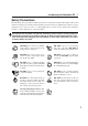
Introducing the Notebook PC 1 Safety Precautions The following safety precautions will increase the life of the Notebook PC. Follow all precautions and instructions. Except as described in this manual, refer all servicing to qualified personnel. Do not use damaged power cords, accessories, or other peripherals. Do not use strong solvents such as thinners, benzene, or other chemicals on or near the surface. Disconnect the AC power and remove the battery pack(s) before cleaning.
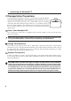
1 Introducing the Notebook PC Transportation Precautions To prepare the Notebook PC for transport, you should turn it OFF and disconnect all external peripherals to prevent damage to the connectors. The hard disk drive’s head retracts when the power is turned OFF to prevent scratching of the hard disk surface during transport. Therefore, you should not transport the Notebook PC while the power is still ON.
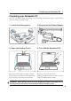
Introducing the Notebook PC 1 Preparing your Notebook PC These are only quick instructions for using your Notebook PC. Read the later pages for detailed information on using your Notebook PC. 1. Install the battery pack 3 2. Connect the AC Power Adapter 3 1 2 1 2 3. Open the Display Panel 4. Turn ON the Notebook PC This Notebook PC features a latchless design. Press the power button and release. Lift the display panel with one hand while holding the system portion with your other hand.
2.
2 Knowing the Parts Top Side Refer to the diagram below to identify the components on this side of the Notebook PC. Details are given starting from the top and going clockwise. Camera Indicator Camera (two positions) Display Panel (Use a soft cloth without chemical liquids to clean. Use plain water if necessary.
Knowing the Parts 2 Camera The built-in camera allows picture taking or video recording. Can be used with voice conferencing and other interactive applications. Display Panel The display panel functions the same as a desktop monitor. The Notebook PC uses an active matrix TFT LCD, which provides excellent viewing like that of desktop monitors. Unlike desktop monitors, the LCD panel does not produce any radiation or flickering, so it is easier on the eyes.
2 Knowing the Parts Bottom Side Refer to the diagram below to identify the components on this side of the Notebook PC. Details are given starting from the top and going clockwise. CPU Compartment Air Vents Battery Pack Battery Lock Battery Lock Memory Compartment Cooling Fan Mini-PCI Compartment Hard Drive Compartment Shutdown Button IMPORTANT! The bottom of the Notebook PC can get very hot. Be careful when handling the Notebook PC while it is in operation or recently been in operation.
Knowing the Parts 2 Central Processor (CPU) Some Notebook PC models feature a socketed-processor design to allow upgrading to faster processors in the future. Some models feature a ULV design for compactness and may not be upgraded. Visit an authorized service center or retailer for information on upgrades. WARNING! End-user removal of the CPU or hard disk drive will void the warranty. Battery Pack The battery pack is actually combined with the Notebook PC’s surface in order to reduce thickness.
2 Knowing the Parts Left Side Refer to the diagram below to identify the components on this side of the Notebook PC. LAN Port Flash Memory Slot USB Port RECORDER Modem Port 1394 Port Optical Drive Activity Emergency Electronic Indicator Eject Eject Modem Port The RJ-11 telephone port supports an RJ-11 telephone cable. The internal modem supports up to 56K V.90 transfers. The built-in connector allows convenient use without a dongle.
Knowing the Parts 2 Right Side Refer to the diagram below to identify the components on this side of the Notebook PC. PC Card Eject Volume Control Mic Input Monitor Port USB Port PC Card Slot Phone Output Air Vents PC Card Slot One PCMCIA 2.1 compliant PC Card socket is available to support one type I/II PC card. The socket supports 32-bit CardBus. This allows accommodation of Notebook PC expansion options such as memory cards, ISDN, SCSI, Smart Cards, and wireless network adapters.
2 Knowing the Parts Rear Side Refer to the diagram below to identify the components on this side of the Notebook PC. USB Port TV-Out Port DC Power Input Jack Battery Pack Kensington® Lock Port Power (DC) Input The supplied power adapter converts AC power to DC power for use with this jack. Power supplied through this jack supplies power to the Notebook PC and charges the internal battery pack. To prevent damage to the Notebook PC and battery pack, always use the supplied power adapter.
Knowing the Parts 2 Front Side Refer to the diagram below to identify the components on the front side of the Notebook PC. Display Panel Tab Camera Camera The built-in camera allows picture taking or video recording. Can be used with voice conferencing and other interactive applications.
2 20 Knowing the Parts
3.
3 Getting Started Power System Using AC Power The Notebook PC power is comprised of two parts, the power adapter and the battery power system. The power adapter converts AC power from a wall outlet to the DC power required by the Notebook PC. Your Notebook PC comes with a universal AC-DC adapter. That means that you may connect the power cord to any 100V-120V as well as 220V-240V outlets without setting switches or using power converters.
Getting Started 3 Using Battery Power The Notebook PC is designed to work with a removable battery pack. The battery pack consists of a set of battery cells housed together. A fully charged pack will provide several hours of battery life, which can be further extended by using power management features through the BIOS setup. Additional battery packs are optional and can be purchased separately through a Notebook PC retailer.
3 Getting Started Powering ON the Notebook PC The Notebook PC’s power-ON message appears on the screen when you turn it ON. If necessary, you may adjust the brightness by using the hot keys. If you need to run the BIOS Setup to set or modify the system configuration, press [F2] upon bootup to enter the BIOS Setup. If you press [Tab] during the splash screen, standard boot information such as the BIOS version can be seen.
Getting Started 3 Checking Battery Power The battery system implements the Smart Battery standard under the Windows environment, which allows the battery to accurately report the amount of charge percentage left in the battery. A fullycharged battery pack provides the Notebook PC a few hours of working power. But the actual figure varies depending on how you use the power saving features, your general work habits, the CPU, system memory size, and the size of the display panel.
3 Getting Started Restarting or Rebooting After making changes to your operating system, you may be prompted to restart the system. Some installation processes will provide a dialog box to allow restart. To restart the system manually, click Windows Start button and select Shut Down and then choose Restart. (Screens are different depending on security settings.
Getting Started 3 Using the Keyboard Colored Hot Keys The following defines the colored hot keys on the Notebook PC’s keyboard. The colored commands can only be accessed by first pressing and holding the function key while pressing a key with a colored command. NOTE: The Hot Key locations on the function keys may vary depending on model but the functions should remain the same. Follow the icons instead of the function keys.
3 Getting Started Microsoft Windows™ Keys There are two special Windows™ keys on the keyboard as described below. The key with the Windows™ Logo activates the Start menu located at the bottom left of the Windows™ desktop. The other key, that looks like a Windows™ menu with a small cursor, activates the properties menu and is equivalent to pressing the right mouse button on a Windows™ object.
Getting Started 3 Buttons and Status Indicators ON OFF Buttons (LCD Panel) Mic Mute Button The Mic Mute button will quickly disable the built-in microphone in order to temporarily block the microsphone while recording a message or using a voicemail/teleconferencing software. Camera Zoom Button The Camera Zoom Button allows you to zoom in or out while using the built-in camera. Camera Button The Camera button allows capturing images with the Notebook PC’s built-in camera.
3 Getting Started Status Indicators (left of touchpad) Power Indicator The power indicator will light to show that the Notebook PC is turned ON and blink when the Notebook PC is in the Suspend-to-RAM (Standby) mode. This LED is OFF when the Notebook PC is OFF or in the Suspend-to-Disk (Hibernation) mode.
Getting Started 3 Status Indicators (top cover) Power Indicator The power indicator will light to show that the Notebook PC is turned ON and blink when the Notebook PC is in the Suspend-to-RAM (Standby) mode. This LED is OFF when the Notebook PC is OFF or in the Suspend-to-Disk (Hibernation) mode.
3 32 Getting Started
4.
4 OS Using the Notebook PC Operating System This Notebook PC may offer (depending on territory) its customers the choice of a pre-installed operating system such as Microsoft Windows XP. The choices and languages will depend on the territory. The levels of hardware and software support may vary depending on the installed operating system. The stability and compatibility of other operating systems cannot be guaranteed.
Using the Notebook PC 4 Pointing Device The Notebook PC’s integrated touchpad pointing device is fully compatible with all two/three-button and scrolling knob PS/2 mice. The touchpad is pressure sensitive and contains no moving parts; therefore, mechanical failures can be avoided. A device driver is still required for working with some application software.
4 Using the Notebook PC Touchpad Usage Illustrations Clicking/Tapping - With the cursor over an item, press the left button or use your fingertip to touch the touchpad lightly, keeping your finger on the touchpad until the item is selected. The selected item will change color. The following 2 examples produce the same results.
Using the Notebook PC 4 Dragging - Dragging means to pick up an item and place it anywhere on the screen you wish. You can move the cursor over the item you select, and while keeping the left button depressed, moving the cursor to the desired location, then release the button. Or, you can simply double-tap on the item and hold while dragging the item with your fingertip. The following 2 examples produce the same results.
4 Using the Notebook PC Storage Devices Storage devices allow the Notebook PC to read or write documents, pictures, and other files to various data storage devices. This Notebook PC has the following storage devices: • PC card • Optical drive • Flash memory reader • Hard disk drive PC Card (PCMCIA) Socket The Notebook PC supports PC Cards (or sometimes referred to as PCMCIA cards) to allow expansion like PCI cards on desktop computers.
Using the Notebook PC 4 Inserting a PC Card (PCMCIA) Be sure the PC card is level when inserting. 1 1. If there is a PC Card socket protector, remove it using the “Removing a PC Card” instructions below. 2. Insert the PC card with the connector side first and label side up. Standard PC cards will be flush with the Notebook PC when fully inserted. 2 3. Carefully connect any cables or adapters needed by the PC card. Usually connectors can only be inserted in one orientation.
4 Using the Notebook PC Optical Drive Inserting an optical disc 3 1 2 1. While the Notebook PC’s power is ON, 2. Gently pull on the drive’s front panel and slide the tray completely out. Be careful not to touch press the drive’s eject button and the tray the CD drive lens and other mechanisms. will eject out partially. Make sure there are no obstructions that may get jammed under the drive’s tray. 4 5 3. Hold the disc by the edge and face the disc’s 4. Slowly push the drive’s tray back in.
Using the Notebook PC 4 Optical Drive (Cont’) Removing an optical disc 3 2 CD -R 1 1. While the Notebook PC’s power is ON, press the drive’s eject button and the tray will eject out partially. 2. While pressing down on the center hub, gently pry the edge of the disc upwards at an angle to remove the disc from the hub. Using the Optical Drive Optical discs and equipment must be handled with care because of the precise mechanics involved.
4 Using the Notebook PC Flash Memory Reader Normally a PCMCIA memory card reader must be purchased separately in order to use memory cards from devices such as digital cameras, MP3 players, mobile phones, and PDAs.
Using the Notebook PC 4 Modem Connection The telephone wire used to connect the Notebook PC’s internal modem should have either two or four wires (only two wires (telephone line #1) is used by the modem) and should have an RJ-11 connector on both ends. Connect one end to the modem port and the other end to an analog telephone wall socket (the ones found in residential buildings). Once the driver is setup, the modem is ready to use.
4 Using the Notebook PC Fast-Ethernet Connection (Gigabit on selected models) Connect a network cable, with RJ-45 connectors on each end, to the modem/network port on the Notebook PC and the other end to a hub or switch. For 100 BASE-TX / 1000 BASE-T speeds, your network cable must be category 5 or better (not category 3) with twisted-pair wiring. If you plan on running the interface at 100/1000Mbps, it must be connected to a 100 BASE-TX / 1000 BASE-T hub (not a BASET4 hub).
Using the Notebook PC 4 Power Management Modes The Notebook PC has a number of automatic or adjustable power saving features that you can use to maximize battery life and lower Total Cost of Ownership (TCO). You can control some of these features through the Power menu in the BIOS Setup. ACPI power management settings are made through the operating system.
4 Using the Notebook PC Power State Summary STATE ENTRY EVENT EXIT EVENT “Stand by” • “Stand by” through Windows Start button, • Timer as set though “Power Management” in Windows Control Panel (higher priority) • Any device • Battery low STR (“Stand by”) (Suspend-to-RAM) STD (“Hibernate”) (Suspend-to-Disk) • Hotkey [Fn][F1] -• Hotkey [Fn][F1] -- • • • • Soft OFF • Power button (can be defined as STR or STD) • Power button • “Shut down” through Windows Start button Signal from modem port Power bu
Using the Notebook PC 4 Stand by and Hibernate Power management settings can be found in the Windows control panel. The following shows the power options properties in Windows. You can define “Stand By” or “Shut down” for closing the display panel, pressing the power button, or activating sleep mode. “Stand by” and “Hibernate” saves power when your Notebook PC is not in use by turning OFF certain components.
4 48 Using the Notebook PC
Appendix Optional Accessories Optional Connections DVD-ROM Drive Information Internal Modem Compliancy Glossary Safety Statements Notebook PC Information 49
A Appendix Optional Accessories These items, if desired, come as optional items to complement your Notebook PC. USB Hub (Optional) Attaching an optional USB hub will increase your USB ports and allow you to quickly connect or disconnect many USB peripherals through a single cable. USB 2.
Appendix A Optional Accessories (Cont.) These items, if desired, come as optional items to complement your Notebook PC. Wireless LAN Card or USB Adapter The ASUS WLAN PC Card (WL-107g) is a wireless LAN adapter that fits into a PCMCIA Type II slot in a Notebook PC and creates a wireless network using the IEEE 802.11g/b wireless standards. 802 .11g 54M bps The ASUS USB Wireless LAN Adapter (WL167g) is thumb-sized and creates a wireless network using the IEEE 802.
A Appendix Optional Accessories (Cont.) These items, if desired, come as optional items to complement your Notebook PC. USB Floppy Disk Drive The Notebook PC features an optional USB-interface disk drive that accepts a standard 1.44MB (or 720KB) 3.5-inch floppy diskette. The eject button is on the top edge of the floppy disk drive for easy access, unlike desktop PCs with the eject button on the bottom of the floppy disk drive.
Appendix A Optional Connections These items, if desired, may be purchased from third-parties. Monitor Out Connection Attaching an optional VGA/LCD monitor is just like that of a standard desktop PC (some configurations may require additional display driver settings. You can view the Notebook PC display panel while simultaneously allowing others to view the external monitor. For large audiences, try you can connect a video projector to this port.
A Appendix Optional Connections (Cont.) These items, if desired, may be purchased from third-parties. IEEE1394 Connection 1394 is a high speed serial bus like SCSI but has simple connections and hot-plugging capabilities like USB. Up to 63 devices such as hard disk drives, scanners, removable drives, and digital cameras/ video cameras with an 1394 port can all be connected (more 1394 devices can be connected using a 1394 hub).
Appendix A Glossary ACPI (Advanced Configuration and Power Management Interface) Modern standard for reducing power usage in computers. APM (Advanced Power Management) Modern standard for reducing power usage in computers. AWG (American Wire Gauge) Gauge AWG Diam (mm) Area (mm2) R (ohm/km) I@3A/mm2 (mA) Gauge AWG Diam (mm) Area (mm2) R (ohm/km) I@3A/mm2 (mA) 46 0.04 0.0013 13700 3.8 24 0.50 0.20 87.5 588 44 0.05 0.0020 8750 6 0.55 0.24 72.3 715 42 41 0.06 0.07 0.0028 0.
A Appendix BIOS (Basic Input/Output System) BIOS is a set of routines that affect how the computer transfers data between computer components, such as memory, disks, and the display adapter. The BIOS instructions are built into the computer’s read-only memory. BIOS parameters can be configured by the user through the BIOS Setup program. The BIOS can be updated using the provided utility to copy a new BIOS file into the EEPROM. Bit (Binary Digit) Represents the smallest unit of data used by the computer.
Appendix A Hardware Hardware is a general term referring to the physical components of a computer system, including peripherals such as printers, modems, and pointing devices. IDE (Integrated Drive Electronics) IDE devices integrate the drive control circuitry directly on the drive itself, eliminating the need for a separate adapter card (in the case for SCSI devices). UltraDMA/66 or 100 IDE devices can achieve up to 33MB/Sec transfer. IEEE1394 Also known as iLINK (Sony) or FireWire (Apple).
A Appendix CLASS 3B: Class 3B lasers, and Class 3A lasers with outputs of 2.5mW, are hazardous to personnel who are within the beam path and look at the beam source directly or by specular reflection. These lasers cannot produce hazardous diffuse reflections. Personnel working with these lasers should wear appropriate protective eyewear during any operation of the laser. Class 3B lasers have both administrative and physical controls to protect personnel.
Appendix A System Disk A system disk contains the core file of an operating system and is used to boot up the operating system. Twisted-Pair Cable The cable used to connect the Ethernet card to a host (generally a Hub or Switch) is called a straightthrough Twisted Pair Ethernet (TPE). The end connectors are called RJ-45 connectors, which are not compatible with RJ-11 telephone connectors. If connecting two computers together without a hub in between, a crossover twisted-pair is required.
A Appendix Declarations and Safety Statements DVD-ROM Drive Information The Notebook PC comes with an optional DVD-ROM drive or a CD-ROM drive. In order to view DVD titles, you must install your own DVD viewer software. Optional DVD viewer software may be purchased with this Notebook PC. The DVD-ROM drive allows the use of both CD and DVD discs. Regional Playback Information Playback of DVD movie titles involves decoding MPEG2 video, digital AC3 audio and decryption of CSS protected content.
Appendix A Internal Modem Compliancy The Notebook PC with internal modem model complies with JATE (Japan), FCC (US, Canada, Korea, Taiwan), and CTR21. The internal modem has been approved in accordance with Council Decision 98/ 482/EC for pan-European single terminal connection to the public switched telephone network (PSTN).
A Appendix Internal Modem Compliancy (Cont.) This table shows the countries currently under the CTR21 standard.
Appendix A Federal Communications Commission Statement This device complies with FCC Rules Part 15. Operation is subject to the following two conditions: • This device may not cause harmful interference, and • This device must accept any interference received, including interference that may cause undesired operation. This equipment has been tested and found to comply with the limits for a class B digital device, pursuant to Part 15 of the Federal Communications Commission (FCC) rules.
A Appendix UL Safety Notices Required for UL 1459 covering telecommunications (telephone) equipment intended to be electrically connected to a telecommunication network that has an operating voltage to ground that does not exceed 200V peak, 300V peak-to-peak, and 105V rms, and installed or used in accordance with the National Electrical Code (NFPA 70).
Appendix A Optical Drive Safety Information Laser Safety Information Internal or external optical drives sold with this Notebook PC contains a CLASS 1 LASER PRODUCT (LASER KLASSE 1 PRODUKT). Laser classifications can be found in the glossary at the end of this user’s manual. WARNING: Making adjustments or performing procedures other than those specified in the user’s manual may result in hazardous laser exposure. Do not attempt to disassemble the optical drive.
A Appendix Nordic Cautions (for Notebook PC with Lithium-Ion Battery) CAUTION! Danger of explosion if battery is incorrectly replaced. Replace only with the same or equivalent type recommended by the manufacturer. Dispose of used batteries according to the manufacturer’s instructions. (English) ATTENZIONE! Rischio di esplosione della batteria se sostituita in modo errato. Sostituire la batteria con un una di tipo uguale o equivalente consigliata dalla fabbrica. Non disperdere le batterie nell’ambiente.
Appendix A CTR 21 Approval (for Notebook PC with built-in Modem) Danish Dutch English Finnish French German Greek Italian Portuguese Spanish Swedish 67
A Appendix Notebook PC Information This page is provided for recording information concerning your Notebook PC for future reference or for technical support. Keep this User’s Manual in a secured location if passwords are filled out.
Copyright information No part of this manual, including the products and software described in it, may be reproduced, transmitted, transcribed, stored in a retrieval system, or translated into any language in any form or by any means, except documentation kept by the purchaser for backup purposes, without the express written permission of ASUSTeK COMPUTER INC. (“ASUS”).
Contact Information ASUSTeK COMPUTER INC. (Asia-Pacific) Company Address: General Telephone: General Fax: 15 Li-Te Road, Peitou, Taipei 112 +886-2-2894-3447 Web Site Address: www.asus.com.tw +886-2-2894-7798 General Email: info@asus.com.