
User's Manual
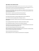

2.Assembly
Warning:Switchoffthegrinderanddisconnectitfromthepowerpoint.
1) Theauxiliaryhandle(1)canbescrewedtotheleftortherightofGearBox.Selectthepositionwhichgives
themostcomfortableandsafeuse.
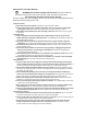
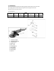
2) Fittingthegrindingguard:(Seefigure1and2)
A:PositionthelugontheinsideofthecentralguardringintheverticalinthespindlecoverthenPlacethe
Wheelguardcoverandrightthehole;
B:Theguardshallbepositionintheneutralposition.
C:Tightenthepanheadscrewinaclockwisedirectionusing
thescrewdriveruntilthescrewistightenup
andthepancannotbemovedanymore.
Figure 1 Figure2
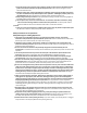
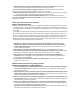
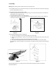
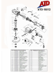
3) Fittingthegrindingdisc:(Figure3andFigure4)
A. Placetheinnerflange(7)overthespindlemakingsurethefitistight
B. Place the grinding disc(8) on the top of the inner flange ensuring the bore fits into the step of the
flange
C. Mounttheconcave
recesssideoftheouterflange(9)overthespindle
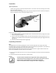
D. Pressthespindlelockingbutton(2)firmandensurethereisnomovementinthespindle.While
thespindlelockisdepressed,tightentheouterflangeinaclockwisedirectionusingthespanner(10).(See
figure4)
Figure 3 Figure 4
Allowtheanglegrindertoruninidleforatleastaminutewiththegrinding,vibrationdiscshouldbe
immediatelyreplaced.