I-Fly Wireless Access Point User’s Manual (V1.
COPYRIGHT The Atlantis Land logo is a registered trademark of Atlantis Land SpA. All other names mentioned mat be trademarks or registered trademarks of their respective owners. Subject to change without notice. No liability for technical errors and/or omissions. Copyright 2002 by this company.
INDEX CHAPITER 1 ............................................................................................................. 1 1.1 AN OVERVIEW OF THE I-FLY WIRELESS ACCESS POINT ................................................................. 1 1.2 PACKAGE CONTENTS ...................................................................................................................... 1 1.3 I-FLY WIRELESS ACCESS POINT FEATURES .................................................................................
APPENDIX B ........................................................................................................... 32 TECHNICAL FEATURES ........................................................................................................................ 32 APPENDIX C .......................................................................................................... 34 GLOSSARY ....................................................................................................................
Chapiter 1 Introduction And' besides available on CDRom a Quick Start Guide for a fast configuration. 1.1 An Overview of the I-Fly Wireless Access Point The device for a total freedom of movement without losing the connection. Easy to be installed and fast and flexible, with I-Fly Wireless Access Point there is no more obligation for a fixed working place: you can easily work or navigate for fun from your own garden or in different rooms of your office, always in wireless connection.
1.3 I-Fly Wireless Access Point Features I-Fly Wireless Access Point provides the following features: • • • • • • • • • • Interoperable with IEEE802.11g and IEEE802.11b Atheros Super G™ capabilities to deliver 108 Mbps raw data rates and 90 Mbps TCP/IP throughput for 802.
● Enables remote access to corporate network information, for example e-mail and the company home page 3
Chapiter 2 Using I-Fly Wireless Access Point 2.1 Cautions for using the I-Fly Wireless Access Point Do not place the AP under high humidity and high temperature. Do not use the same power source for AP with other equipment. Do not open or repair the case yourself. If the AP is too hot, turn off the power immediately and have a qualified serviceman repair it. Place the AP on a stable surface.
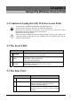
2.4 Cabling The most common problem is bad cabling. Make sure that all connected devices are turned on. On the front of the product is a bank of LEDs. As a first check, verify that the LAN/WLAN(if connected) Link and Power line LEDs are lit.
Chapiter 3 Configuration The I-Fly Wireless Access Point can be configured with your Web browser. The web browser is included as a standard application in the following operation systems, UNIX, Linux, Mac OS, Windows 95/98/NT/2000/Me/XP, and etc. The product provides a very easy and user-friendly interface for configuration. With 3.
3.3 Test TCP/IP After configuring the TCP/IP protocol, you can use the ping command to check if your computer has successfully connected to this AP. The following example shows the ping procedure for Windows 98 . First, execute the ping command. Ping 192.168.1.1 If the following messages appear: Pinging 192.168.1.1 with 32 bytes of data: Reply from 192.168.1.1: bytes=32 times<10ms TTL=64 Reply from 192.168.1.1: bytes=32 times<10ms TTL=64 Reply from 192.168.1.
3.5 Factory Default Settings Before configurating this AP, you need to know the following default settings. Web Configurator Username : admin Password: admin Device IP Network settings in LAN site IP Address : 192.168.1.1 Subnet Mask : 255.255.255.0 DHCP server : DHCP server disable Wireless Channel=6 WEP/WAP=disable 3.5.1 LAN and WAN Port Addresses The parameters of LAN and WAN ports are pre-set in the factory. The default values are shown below. LAN Port IP address 192.168.1.
The below window will popup. Please enter the user name and password. Both of the default is “admin”. Now, the main menu screen is popup.
At the configuration homepage (if Quick Setup Wizard starts, please close it or read the printed Quick Start Guide), the left navigation page where bookmarks are provided links you directly to the desired setup page, including: • Wizard • Status • Basic Setting • IP Setting • Advanced Setting • Security • 802.1x • Tools Click on the desired item to expand the page in the main navigation page. 3.7.1 Status This page as below shows you the following information.
• • Wireless: Shows the Mac address, current ESSID, the status of Encryption Function (Enable or Disable), the current using channel. The current wireless traffic calculated in terms of number of packets sent and received by AP through wireless communication is also displayed. View Log: Upon clicked, the page will change to log page. The log page records every event and the time that it happens.
• • • • • • • • AP Name: The name of the AP, which can be used to identify the Access Point among the all the Access Points in the wireless network. SSID: Service Set Identifier, which is a unique name shared among all clients and nodes in a wireless network. The SSID must be identical for each clients and nodes in the wireless network. Channel: The channel that AP will operate in.
3.7.3 IP Settings This page allows you to configure the IP and DHCP settings of the Access Point. The default IP address of this access point is 192.168.1.1 with the subnet mask of 255.255.255.0. You can type in other values for IP Address, Subnet Mask and Gateway and click “Apply” button for the changes to be effective. You can also set the Access Point to obtain the IP from a DHCP server, but it is not recommended.
3.7.4 Advanced Setting This page contains configurations for advanced users, which the change reflects the wireless performance and operating modes. 3.7.4.1 Mode Settings Select one of the AP operating modes for different application of Access Point. 1 AP: The normal Access Point operating mode which forms a wireless ESS network with its wireless clients. In figure an example of configuration.
2 AP Client: Acts as an Ethernet-to-Wireless Bridge, which allows a LAN or a single computer station (no driver installation is need) to join a wireless ESS network through it. You must make sure SSID and Channel is set the same as that AP you wish to connect. Remote AP SSID: key in the LAN Mac address (NOT wireless Mac address) of the AP that you wish to get connected. Please note that if you leave Mac address as 000000000000, then you will get connected by the SSID that is set in you AP.
3 Wireless Bridge: A pair of APs operating under Bridge mode to act as the bridge that connect two Ethernet networks or Ethernet enabled clients together. You must make sure that the SSID and Channel is set the same as that AP you wish to connect. Remote Bridge MAC filed: key in the LAN Mac address (NOT wireless Mac address) of the AP that you wish to get connected.
5 Repeat Mode: It is able to extend the effective range and coverage of the wireless network. Please make sure the SSID is the same as that AP you want to extend. Wireless LAN is Half Duplex, so one transaction pass-through 2 wireless its real data-rate will be half of normal one. 3.7.4.2 Wireless Advanced Settings This screen enables you to configure advanced wireless functions. • • • • • • • • Beacon Interval: Type the beacon interval in the text box. You can specify a value from 1 to 1000.
• ‘SuperG based’ product is available. If no, the connection is via ‘normal’ G. Static turbo means it will not go back to ‘normal’ G once it starts Antenna Power Transmit: Select the Antenna Power transmit for wireless interface. 3.7.5 Security This page is where you configure the security features supported by this Access Point. 3.7.5.1 Password This screen enables you to set administrative and user passwords. These passwords are used to gain access to the AP interface.
MAC Filter: MAC Filter function controls the MAC of the network devices that are listed in this table for access authorization or denial. When MAC Filter is enabled, by selecting the “Enabled” radio box, select one of two choices: Only deny PCs with MAC listed below to access device Only allow PCs with MAC listed below to access device The maximum number of MAC addresses that can be stored is 50. You can browse through the MAC address saved by selecting the drop-down box.
• • • Enable 802.1x security by selecting “Enable”. If MD5 EAP method is used then you can skip step 2 and go to step 3. Select the Encryption Key Length Size ranging from 64 to 128 Bits that you would like to use. Select the Lifetime of the Encryption Key from 5 Minutes to 1 Day. As soon as the lifetime of the Encryption Key is over, the Encryption Key will be renewed by the Radius server. • Enter the IP address, the Port and the Shared Secret used by the Primary Radius Server.
3.7.7.1 (Save/Load)Settings • Backup Settings: Click on “Backup” button, which will open a FileSave Dialog box, where you get to save all the current settings and configurations to a file. • Restore Settings: Click on the “Browse” button to open a FileOpen Dialog box, where you get to select the file, which you save previous settings and configurations. Upon selecting the saved file, click “Restore” and complete the restore process when the access point re-operates after it restarts.
3.8 Configuration through AP Utility (Optional) Launch Setup.exe (CDRom:\Utility\setup.exe) to install tha AP Utility. 3.8.1 Link Information Link information is showing you the related current setting of the first.
23
3.8.2 AP Settings Basic Setting: • ESSID: It is used by all wireless devices within the wireless network. • Channel: Select the appropriate channel from the dropping list. All wireless devices with the same ESSID will automatically use this channel to communicate with this access point. • AP Name: users can set the name for access point so as to easily manage the access points while there are several access points in the network.. Mode Setting: • Access Point:This is the default for this access point.
• Repeat Mode:It is able to extend the effective range and coverage of the wireless network. Please make sure the SSID is the same as that AP you want to extend. 3.8.2.1 Advanced Settings • • • • • • • • SSID Broadcast: While SSID Broadcast is enabled, all wireless clients will be able to communicate with the access point. For secure purpose, you may want to disable SSID broadcast to allow only those wireless clients with the AP SSID to communicate with the access point.
indicates the combination of two channels to enhance the throughput. Super G without turbo indicates that it is on Super G mode without the channel’s combination. Dynamic turbo is able to automatically detect if any ‘SuperG based’ product is available. If no, the connection is via ‘normal’ G.. Static turbo means it will not go back to ‘normal’ G once it starts. 3.8.3 IP Settings • • • Fixed IP Address: Users can assign a fixed IP address to this AP manually.
3.8.4 Security • • Data Encryption: please tick it if you like to have WEP key as the encryption mechanism. Authentication Mode: The authentication type default is set to open system. There are four options: open system; shared key; WPA; WPA-PKS. You may want to set to Shared Key when the clients and AP in the same wireless network enable the WEP encryption. All the nodes and hosts on the network must use the same authentication type. • WEP Key: To disable WEP security, click on the “Disable” option.
3.8.5 802.1X Settings There are three essential components to the 802.1x infrastructure: (1) Supplicant, (2) Authenticator and (3) Server. The Access Point serves as an Authenticator, and the EAP methods used must be supported by the backend Radius Server. The 802.1x security supports MD5 and TLS Extensive Authentication Protocol (EAP). Please follow the steps below to configure 802.1x security.
If users like to set 802.1X or the authentication type is set to WPA, please enable 802.1X function by ticking it. • Encryption Key: Select the Encryption Key Length Size ranging from 64 to 128 Bits that you would like to use. • Lifetime: Select the Lifetime of the Encryption Key from 5 Minutes to 1 Day. As soon as the lifetime of the Encryption Key is over, the Encryption Key will be renewed by the Radius server.
APPENDIX A Super G SuperG™ is an assemble of solutions that are Atheros® properties .They allow you to obtain performances far superior to the IEEE802.11g standard . Performance Atheros® chip which has been purposely developed for the property technology of SuperG™, reaches a performance boost never seen before , reaching results that are even doubled contrasted with the ones from IEEE802.11g devices .
Maximum theoretical limits* Standard Channel Modulation Max LinkRate 11Mbps 54Mbps Max Throughput(TCP) 5.9 Mbps 14.4 Mbps Max Throughput(UDP) 7.1 Mbps 19.5 Mbps 3 CCK 802.11b CCK/OFDM 802.11b and 3 802.11g CCK/OFDM 54Mbps 24.4 Mbps 30.5 Mbps 802.11g only 3 1 OFDM 108Mbps 42.9 Mbps 54.
APPENDIX B Technical Features Physical Interfaces LAN: 1 RJ45 10/100 Base-TX Fast Ethernet Wireless 54Mbps (IEEE802.11g) and 11Mbps (IEEE802.11b) 3 Led for easy diagnostic Reset Wireless Interface Chipset Atheros™ Dipole External removable (reverse SMA) Antenna Radio Spec. Standard IEEE802.11g and IEEE802.11b DSSS(Direct Sequence Spread Spectrum) Modulation: QPSK / BPSK / CCK and OFDM RF Frequency:2.400 GHz ~2.4835GHz Operating Channel:: 13 (Europe) Data Rate (with automatic adaptation): 802.
Physical and Environmental Power Consumation: (5V ± 5%, 2.
APPENDIX C Glossary Access Point An interview networking device that seamlessly connects wired and wireless networks Authentication Authentication refers to the verification of a transmitted message’s integrity. DMZ DMZ (DeMilitarized Zone) is a part of a network that is located between a secure LAN and an insecure WAN. DMZs provide a way for some clients to have unrestricted access to the Internet.
FTP FTP (File Transfer Protocol) is used to transfer files over a TCP/IP network, and is typically used for transferring large files or uploading the HTML pages for a Web site to the Web server. Gateway Gateways are computers that convert protocols enabling different networks, applications, and operating systems to exchange information. Host Name The name given to a computer or client station that acts as a source for information on the network.
MTU MTU (Maximum Transmission/Transfer Unit) is the largest packet size that can be sent over a network. Messages larger than the MTU are divided into smaller packets. NAT NAT (Network Address Translation - also known as IP masquerading) enables an organization to present itself to the Internet with one address. NAT converts the address of each LAN node into one IP address for the Internet (and vice versa).
RTS RTS (Request To Send) is a signal sent from the transmitting station to the receiving station requesting permission to transmit data. Server Servers are typically powerful and fast machines that store programs and data. The programs and data are shared by client machines (workstations) on the network. SMTP SMTP (Simple Mail Transfer Protocol) is the standard Internet e-mail protocol. SMTP is a TCP/IP protocol defining message format and includes a message transfer agent that stores and forwards mail.
APPENDIX D Support If you have any problems with the Wireless AP, please consult this manual. If you continue to have problems you should contact the dealer where you bought this AP. If you have any other questions you can contact the Atlantis Land company directly at the following address: AtlantisLand spa Via De Gasperi 122 20017 Mazzo di Rho(MI) Tel: 02/93906085, 02/93907634(help desk) Fax: 02/93906161 Email: info@atlantisland.it or tecnici@atlantisland.it WWW: http://www.atlantisland.it or www.