
Instructions / Assembly


6
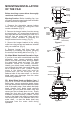
Figure 13
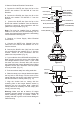
Figure 12
Outlet box
Hanger
bracket
Canopy
Canopy cover
Screws
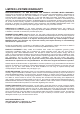
2. Motor to Receiver Electrical Connections:
A. Connect the WHITE wire from the fan to the
WHITE wire marked "TO MOTOR N" from the
Receiver.
B. Connect the BLACK wire from the fan to the
BLACK wire marked "TO MOTOR L" from the
Receiver.
C. Connect the BLUE wire from the fan to the
BLUE wire marked "oscillation" from the Receiver.
Proceed to secure all wire connections with the
plastic wire nuts provided. (Fig. 12)
Note: Fan must be installed from a maximum
distance of 40 feet from the transmitting unit for
proper signal transmission between the transmitting
unit and the fan's receiving unit.
3. Receiver to House Supply Wires Electrical
Connections:
A. Connect the WHITE wire (Neutral) from the
outlet box to the WHITE wire marked "AC in N"
from the receiver.
B. Connect the BLACK wire (Hot) from the outlet
box to the BLACK wire marked "AC in L" from the
receiver. Secure all wire connections with the
plastic wire nuts provided. (Fig. 12)
4. If your outlet box has a GROUND wire (Green or
Bare Copper) connect this wire to the Hanger Ball
and Hanger Bracket Ground wires. If your outlet
box does not have a Ground Wire, then connect
the Hanger Ball and Hanger Bracket Ground Wires
together. Secure wire connection with the plastic
wire nut provided. (Fig. 12)
5. Tuck connections neatly into ceiling outlet box.
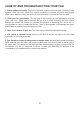
6. Slide the canopy up to hanger bracket and place
the key hole on the canopy over the screw on the
hanger bracket, turn canopy until it locks in place at
the narrow section of the key holes. (Fig. 13)
7. Align the circular hole on canopy with the
remaining hole on the hanger bracket, secure by
tightening the two set screws. Note: Adjust the
canopy screws as necessary until the canopy and
canopy cover are snug.
Warning: Make sure tab at bottom of hanger
bracket is properly seated in groove of hanger ball
before attaching canopy to bracket. Failure to
properly seat tab in groove could cause damage to
electrical wiring.
WHITE (NEUTRAL)
WHITE (NEUTRAL)
GREEN OR BARE
COPPER (GROUND)
WHITE ("AC IN N")
WHITE ("TO MOTOR N")
GROUND-
(GREEN)
(3 GROUND WIRES
ON CEILING FAN)
OUTLET BOX
BLACK (HOT)
BLACK ("AC IN L")
BLACK ("TO MOTOR L")
RECEIVER
BLUE (
OSCILLATION
)
BLUE (
OSCILLATION
)
BLACK (MOTOR)