Eliza Hugger 56” CEILING FAN READ AND SAVE THESE INSTRUCTIONS FAN RATING AC 120V. 60Hz Please do not use any electric or battery powered tools in the assembly and installation of this or any Matthews Fan Company product.
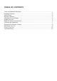
TABLE OF CONTENTS Tools and Materials Required.........................................................................................1 Package Contents ......................................................................................................... 1 Safety Rules................................................................................................................... 2 Mounting Options........................................................................................................
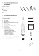
1. TOOLS AND MATERIALS REQUIRED Philips screwdriver Blade screwdriver 11 mm wrench Step ladder Wire cutters 2. PACKAGE CONTENTS c Unpack your fan and check the contents. You should have the following items: a. b. c. d. e. f. g. h.
3. SAFETY RULES 1. To reduce the risk of electric shock, insure electricity has been turned off at the circuit breaker or fuse box before beginning. 8. To avoid personal injury or damage to the fan and other items, be cautious when working around or cleaning the fan. 2. All wiring must be in accordance with the National Electrical Code and local electrical codes. Electrical installation should be performed by a qualified licensed electrician. 9.
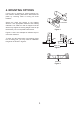
4. MOUNTING OPTIONS If there isn't an existing UL listed mounting box, then read the following instructions. Disconnect the power by removing fuses or turning off circuit breakers. Secure the outlet box directly to the building structure. Use appropriate fasteners and building materials. The outlet box and its support must be able to fully support the moving weight of the fan (at least 35 lbs). Do not use plastic outlet boxes.
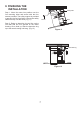
5. ATTACHING THE FAN BLADES Screws 1. Remove the motor housing from the fan motor by removing the two screws from the rim of motor housing. (Fig. 4) Motor housing 2. Attach the blade holder to the blades using the screws provided. Repeat process with other blades. (Fig. 5) Collar 3. Fasten the blade assembly to the fan motor using the blade screws supplied. Repeat process with other blades. Tighten each screw and make sure the blade is straight. (Fig.
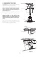
6. HANGING THE FAN Decorative ring Screws REMEMBER to turn off the power. Follow the steps below to hang your fan properly: Step 1. Replace the motor housing to the fan motor by using the screws previously removed. Slide the decorative ring down and through the motor housing. (Fig. 7) Motor houaing Step 2. Attach the mounting bracket to the outlet box using the two screws and washers provided with the outlet box.
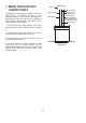
7. MAKE THE ELECTRIC CONNECTIONS Outlet box White ("AC IN N") Green or bare copper (ground) Black ("AC IN L") Remember to disconnect the power. Follow the steps below to connect the fan to your household wiring. Use the wire connecting nuts supplied with your fan. Secure the connectors with electrical tape. Make sure there are no loose strands or connections. Black (motor) Ground (green) (Connect to ground wire on hanger bracket if no house ground wire exists.) White (neutral) 1.
8. FINISHING THE INSTALLATION Safety cable Step 1. Move fan motor into position over the four mounting holes and secure with the four screws provided. The safety support is provided to prevent the fan from falling. Secure the safety cable securely onto the hook. (Fig. 11) Screws Motor Step 2. Raise up decrotive ring and line up the four tabs with the four grooves on the motor housing. Once lined up, slide the decrotive ring up to the motor housing until snug. (Fig.
9. PROGRAMMING YOUR FAN AND OPERATING THE REMOTE CONTROL Your DC brushless motor is equipped with a automatically learned type remote control. Before programming takes place, fan must be fully assembled and mounted to the ceiling with blades attached. Install one 23A/12V battery (included). To prevent damage to transmitter, remove the battery if not used for long periods of time (Fig. 13) ON ECE 1 2 3 4 Restore power to ceiling fan and test for proper operation. Figure 13 A.
NOTE: During self calibration test, the remote is non-fuctional. NOTE: The learning frequency function and calibration test will continue to retain the last frequency and calibration set even when the power is shut off. If the frequency is changed self calibration test will occur again. self set AC the This receiver provides the following protective function: 1. Lock Rotor Position: The DC motor has a built-in safety against a stalled or locked rotor condition (stalled blade rotation).
11. CARE OF YOUR FAN Here are some suggestions to help you maintain your fan 1. Because of the fan's natural movement, some connections may become loose. Check the support connections, brackets, and blade attachments twice a year. Make sure they are secure. (It is not necessary to remove fan from ceiling.) 2. Clean your fan periodically to help maintain its new appearance over the years. Use only a soft brush or lint-free cloth to avoid scratching the finish.
LIMITED LIFETIME WARRANTY MATTHEWS-GERBAR, LTD. DBA MATTHEWS FAN COMPANY LIFETIME LIMITED WARRANTY. Ceiling fans are warranted by Matthews-Gerbar, Ltd. to the original user against defects in workmanship or materials under normal use and inside installation for: Motors: Lifetime of original purchaser: Labor & Component parts: (lights, finish, blades, etc…): one year after date of purchase, Light Bulbs: no warranty. Any part, which is determined by Matthews-Gerbar, Ltd.