
User`s manual


5
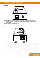
INSTALLATION
CONNECTION DIAGRAM
1. Connect a HDMI
™
or DVI Sender Unit such as AT-HD-V40SS, AT-HD14SS, AT-HD19SS, AT-
HD50SS, AT-HD50RSL, AT-DVI40SRS with a solid Cat5/5e/6/7 UTP/STP cable to the
CAT5/6/7 INPUT RJ45 port.
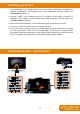
2. Connect a HDMI
™
or DVI Receiver Unit such as AT-HDRP, AT-HD-V40RS, AT-HDRS, AT-
HD15SRS, AT-DVI15SRS, and AT-DVI40RS with a solid Cat5/5e/6/7 UTP/STP cable to the
CAT5/6/7 OUTPUT RJ45 port.
3. Make sure the solid Cat5/5e/6/7 UTP/STP cables are tightly connected and not loose.
4. Plug in the 5V DC power supply unit to the locking power jack.
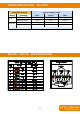
5. If you see flickering or blinking image on the display, adjust the rotary control switch to improve
the cable skew. MAX stands for the strongest HDMI
™
signal level for longest possible
transmission length while MIN stands for the weakest HDMI signal level for short transmission
length. Try adjusting the signal level from MIN to MAX to find the optimal setting.