C51 Microcontrollers Demo Board ..............................................................................................
Table of Contents Section 1 Introduction ........................................................................................... 1-2 1.1 1.2 C51/C251 Support ....................................................................................1-2 Demo Board Features...............................................................................1-3 Section 2 Hardware Description ........................................................................... 2-4 2.1 2.2 2.3 2.4 2.5 2.6 Block Diagram........
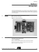
Introduction Section 1 Introduction The C51/C251 Demo Board allows easy evaluation of most of Atmel C51/C251 devices. The C51/C251 Demo Board can be powered using a simple 9V battery or using a 9V rechargeable battery. The C51/C251 Demo Board can also be used as programming tool for Flash products. 1.1 Package Contents n One PCB C51/C251 Demo Board (with battery connector) n One Serial cable (1.8m length) Figure 1-1. C51/C251 Demo Board 1.
Introduction 1.3 Support Questions can be sent to: mcu@atmel.com 1.
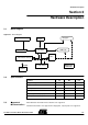
Hardware Description Section 2 Hardware Description 2.1 Block Diagram Figure 2-1. Block Diagram Synchro connectors RS232 Reset & INT1# C51/C251 Bargraph LCD 2*16 Glue 128 K Flash memory To All Config switches Extensions connector Power interface 2.2 Specifications Parameter 2.
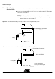
Hardware Description 2.4 Board Supply Considerations n Power connector J1 or battery connector J2 may be used to power the board. n On J2 connector a rechargeable battery or a non-rechargeable battery may be used. n In case of rechargeable battery usage on J2, if J18 is ON the battery is charged when the board is powered by J1. n Board may be powered by J2 for about 10 hours with one new non-rechargeable battery.
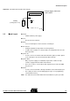
Hardware Description Figure 2-4. C51/C251 Demo Board Powered by J2. LCD display J1 Power Supply Connector NOT USED J2 J18 battery (rechargeable or not) 2.5 Board Layout ON 9V PP3 n On-Off – Switches ON the power supply. n Reset – Resets the microcontrollers. n INT1# – Issues an interruption on microcontollers on INT1# pin. n J8 Connector – Configure hardware in Page Mode or Non Page Mode. – for C251 microcontrollers. For C51 products, the configuration must be set to Non Page Mode.
Hardware Description Figure 2-5. C51/C251 Demo Board RS232 Cable to Terminal RS232 R21 + LCD CTRST LCD J11 J17 OFF Synchro IN ON RESET Synchro OUT J8 J9 INT1 J16 1 1 Page Mode 1 X2 PLCC44 J8 X1 X3 Non Page Mode DIL24 PLCC68 Extension connector 2.6 J11 Switches Table 1.
Hardware Description Table 2. J9 Switches Bit Number 0 MAP SELECT EA Bit Mnemonic Description MAP SELECT 1 1 Map Select Set to select external Flash memory zone from $10000 to $1FFFF Clear to select external Flash memory zone from $00000 to $0FFFF External Address 0 EA Set to fetch internal code (on chip code). Clear to fetch code from external Flash memory Table 3.
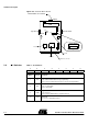
Operation Mode Section 3 Operation Mode 3.1 Flash Products 3.1.1 Switch Configuration To program the on-chip Flash memory, hardware configuration of the chip should be the following: PSEN = 0, EA = 1 and ALE = 1 or not connected. On C51/C251 Demo Board, switches must be as shown on Figure 3-2. Figure 3-1. C51/C251 Demo Board Switches Configuration to use ISP RS232 Cable to PC Position don’t care J11 User Code Position needed PSEN ALE ISP1 J11 1 J9 J9 1 0 0 EA MAP SELECT J16 ISP2 J16 3.
Operation Mode 3.2 ISP External Flash Memory Mode External Flash memory might be programmed using Windows hyper terminal or any terminal able to send HEX files in text mode. 3.2.1 Hardware Configuration The C51/C251 Demo Board must be connected to the PC com port with the cable connected to the RS232 connector J10. The switch must be set as shown on Figure 3-2. PLCC44 socket and X1 Quartz crystal will be used to program external Flash memory. X1 must be 11.
Operation Mode Figure 3-3. Com Port Configuration Figure 3-4. Terminal Window on Running ISP Turn on the C51/C251 Demo Board and then follow the instructions on the terminal screen and LCD display. After erasing Flash, the program asks for the memory zone, and then asks to send the HEX file in text mode (see Figure 3-4, Figure 3-5 & Figure 36).
Operation Mode Figure 3-5. Send HEX File in Text Mode Figure 3-6. Use *.
Operation Mode After the download of the HEX file, the program asks if you want to download another HEX file in the second zone of the external Flash memory. In this case you’ll have to switch MAP SELECT (to access second zone) and send another HEX file in text mode. All the external flash memory (128K bytes) is erased when ISP is used, even if you only want to download one zone.
Operation Mode Figure 3-8. C51 Mode (Non Page Mode) J11 J8 NON PAGE MODE J9 J16 3.3.2 C251 Mode In C251 mode, the microcontroller can be used in Page Mode or Non Page Mode. For Non Page Mode switch J8 must be in the same configuration as in C51 mode. For Page Mode switch J8 must be as shown in Figure 3-9. Figure 3-9.
Bill of Material Section 4 Bill of Material Reference Type C1-C28 POL_CAPACITOR 4,7uF Qty 2 CMS_TAJ_Package_B Comment C2:C10-C19:C23 CAPACITOR 100nF 14 Package_0805 C11 POL_CAPACITOR 3,3uF 1 TAJ_CMS_Package_B C12 POL_CAPACITOR 10uF 1 TAJ_CMS_Package_B C13-C14-C24:C27 CAPACITOR 22pF 6 Serie_680 C15:C18 POL_CAPACITOR 10uF 4 CMS_TAJ_Package_B D1-D14 1N4001 1N4001 2 Package_DO204AL D2-D11:D13 LED LED 4 CMS_STANDART D3:D6 LED_GREEN GREEN LED 1 in_line_2.
Section 5 Schematics C51 Demo Board User Guide 5-18 Rev.
Schematics 5-19 4119C–8051–3/03 C51 Demo Board User Guide
Schematics C51 Demo Board User Guide 5-20 4119C–8051–3/03
Schematics 5-21 4119C–8051–3/03 C51 Demo Board User Guide
Schematics C51 Demo Board User Guide 5-22 4119C–8051–3/03
Schematics 5-23 4119C–8051–3/03 C51 Demo Board User Guide
Atmel Headquarters Atmel Operations Corporate Headquarters Memory 2325 Orchard Parkway San Jose, CA 95131 TEL 1(408) 441-0311 FAX 1(408) 487-2600 Europe Atmel SarL Route des Arsenaux 41 Casa Postale 80 CH-1705 Fribourg Switzerland TEL (41) 26-426-5555 FAX (41) 26-426-5500 Asia Atmel Asia, Ltd. Room 1219 Chinachem Golden Plaza 77 Mody Road Tsimhatsui East Kowloon Hong Kong TEL (852) 2721-9778 FAX (852) 2722-1369 Japan Atmel Japan K.K. 9F, Tonetsu Shinkawa Bldg.