Atmos InterCombi Installation & Servicing Instructions for HE32 (GC 47-249-01) Atmos Heating Systems West March Daventry Northants, NN11 4SA Tel: 01327 871990 Fax: 01327 871905 e-mail: sales@atmos.co.uk internet: www.atmos.co.uk Issue 01.11.
© 2011 Atmos Heating Systems The information provided applies to the product in the standard model. Atmos Heating Systems can therefore not be held liable for any damage resulting from the product specifications that deviate from the standard model. The information provided has been compiled with the utmost care. However, Atmos Heating Systems cannot be held liable for any faults in the information nor for the consequences thereof.
TABLE OF CONTENTS 1. Safety Regulations 7 1.1 General ....................................................................................................................................................................... 7 1.2 CH system................................................................................................................................................................... 7 1.3 Gas system .............................................................................................
8.3 8.4 8.5 8.6 8.7 8.8 8.9 9. Burner ignites with much noise ................................................................................................................................. 45 Burner resonates....................................................................................................................................................... 46 No heating (CH) .................................................................................................................................
This manual Using this manual you can safely install and maintain this appliance. Carefully follow the instructions. In case of doubt, contact Atmos Heating Systems. Keep these instructions near the appliance.
Atmos Warranty – Short version 1. 2. 3. 4. 5. 6. 7. Atmos Warranty covers any material, construction or operation faults that are found to be of original manufacturing origin. A full statement of the Atmos Warranty can be found on www.atmos.co.uk. Atmos boiler warranty is two years from date of invoice or 12 months from date of installation, whichever is the later. This warranty covers the cost of replacement parts and associated labour.
1. SAFETY REGULATIONS The appliance must be installed by a Gas Safe registered person in accordance with the current Gas Safety (Installation and Use) Regulations. Failure to install appliances correctly could lead to prosecution. Atmos Heating Systems does not accept any liability for damage or injury caused by not (strictly) observing the current safety regulations and instructions, nor by negligence while installing the Atmos InterCombi wallmounted gas heater and any accompanying accessories.
2. DESCRIPTION OF THE APPLIANCE 2.1 General The Atmos InterCombi wall-mounted gas boiler is designed for delivering heat to the water of a CH system and the domestic hot water. The air supply and flue discharge can be connected to the appliance by means of two separate pipes or a concentric connection. The appliance has its own wall mounting strip, but can also be fitted to an optional wall mounting frame that allows top connections.
Waiting position The LED of the on/off button is on and depending on the keep-hot setting, one of the LED’s of the domestic hot water keep-hot function may also be on. The appliance is ready for responding to the demand for CH or domestic hot water. 0 Pump overrun After CH operation the pump has an overrun. This overrun time is set to the value according to parameter 8 (see §7.3; factory setting is 1 min). This setting can be changed.
determined by the weather dependent control programmed in the controller. During CH operation, the demanded CH supply temperature is displayed on the operating panel. During CH operation, the actual CH supply temperature can be read by pressing the service button. Note: Instead of an on/off thermostat, an OpenTherm thermostat can be connected to the controller as described in §5.4.1. In this case, the desired CH temperature is set by the thermostat.
2.5 Test programmes In the controller, there is provision for putting the appliance into a test status. By activating a test programme, the appliance will become active with a fixed fan speed without intervention of the control functions. The safety functions remain active though. Simultaneously press + and – to switch off the test programme.
3.
3.1 Accessories Description Pipe mounting bracket • Connection supply and return 22 mm diameter • Connection cold and hot water 15 mm diameter • Connection gas ½" female thread • Mounting strip boiler • Bag with fixings Rear mounting frame for top pipe connection Bottom Pipework cover Outside sensor for weather compensation Conversion set to Propane (LPG or G31) Interface cable (for Installers) Part Ref 092.
4. INSTALLATION 4.
4.2 Unpacking the appliance 1. 2. Unpack the appliance. Check the content of the packaging. This consists of:• Appliance (A) • Mounting strip (B) • Condensate trap (C) • Installation Instructions • User Operating Instructions • Warranty card 3. Valve set (supplied separately with boiler) comprising 2 x 22mm isolation valves, 1 x 15mm flow regulating isolation valve with blue lever (for cold water), 1 x gas valve. 4. Check the appliance for any damage: report damage to the Supplier immediately.
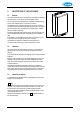
4.4 Boiler location Clearances Above casing 200mm min Below casing 230mm min RH 30mm min LH 30mm min (in operation) LH 140mm min (servicing) Front 30mm min (in operation) Front 450mm min (servicing) Keep 50 mm free space above the front panel in order to be able to remove the front panel from the casing. Allow 140 mm on the left side for swinging out the expansion vessel during commissioning/service. The appliance can be fitted to a mounting frame.
4.5 Mounting and General Information Depending on the mounting option ordered, the following mounting methods are available:Mounting strip (A) alone, OR mounting strip (A) and optional pipe mounting bracket (B), OR rear mounting frame (C) and pipe mounting bracket (B), which are both optional items. This arrangement allows for vertical pipework behind the boiler. Note that when the pipe mounting bracket is used, the pipes can be connected before installing the appliance. A 4.5.1 1. 2.
4.5.4 1. 2. 3. Installation connections Make the various connections to the valves (see diagram). Install a filling loop (not supplied) between the cold water inlet pipe and the CH return connection. For most installations, the flexible tube for the safety discharge will be long enough to fit into the condensate discharge waste pipe (see below). In cases where this does not apply, install a 15 mm copper safety discharge pipe to fit into the waste pipe (as shown in the diagram, §5.
4.8 Condensate disposal The appliance is provided with a 25 mm flexible pipe from its condensate trap. As given in §Error! Reference source not found., this should be inserted into an open waste pipe of not less than 32 mm diameter, together with the safety discharge pipe.
5. CONNECTIONS 5.1 Connect the CH system 1. 2. Flush the CH system thoroughly. Connect the flow and return pipes using the 22mm isolation valves. All pipes must be mounted tension-free in order to avoid ticking of the pipes. Existing connections must not be twisted in order to avoid leaks at the connections with the external pipes. The CH system should be provided with:• A filling loop in the return pipe directly below the appliance. • A drain tap at the lowest point of the system.