V.92 56K Internal Modem User’s Guide C6628-0702M1 TOSHIBA 5.375 x 8.375 ver 2.4.
FCC Notice “Declaration of Conformity Information” This equipment has been tested and found to comply with the limits for a Class B digital device, pursuant to Part 15 of the FCC rules. These limits are designed to provide reasonable protection against harmful interference in a residential installation. This equipment generates, uses and can radiate radio frequency energy and, if not installed and used in accordance with the instructions, it may cause harmful interference to radio communications.
Industry Canada Requirement This Class B digital apparatus complies with Canadian ICES-003. Cet appareil numérique de la classe B est conformé à la norme NMB-003 du Canada.
in advance of this disconnection. If advance notice is not feasible, you will be notified as soon as possible. When you are notified, you will be given the opportunity to correct the problem and informed of your right to file a complaint with the FCC. In the event repairs are ever needed on your modem, they should be performed by Toshiba Corporation or an authorized representative of Toshiba Corporation.
water pipe system, if present, are connected together. This precaution may be particularly important in rural areas. Caution: Users should not attempt to make such connections themselves, but should contact the appropriate electric inspection authority, or electrician, as appropriate. 2 The user’s guide of analog equipment must contain the equipment’s Ringer Equivalence Number (REN) and an explanation notice similar to the following: The Ringer Equivalence Number (REN) of this device can vary.
Toshiba assumes no liability for damages incurred directly or indirectly from errors, omissions or discrepancies between the modem and the user’s guide. Trademarks Microsoft and Windows are registered trademarks of Microsoft Corporation. Microcom and Microcom Networking Protocol are registered trademarks of Microcom, Inc. Hayes is a registered trademark of Hayes Microcomputer Products Inc. MNP is a trademark of Microcom Systems, Inc. 5.375 x 8.375 ver 2.4.
Contents Introduction ..............................................................12 Conventions ........................................................... 12 Features ................................................................. 14 Function charts ...................................................... 17 Chapter 1: Modem On Hold....................................... 19 Using Modem On Hold........................................... 20 Answering an incoming voice call....................
Contents Chapter 3: Using the Internal Modem ....................... 44 Connection procedures .......................................... 44 Analog or digital?............................................. 45 Connecting the internal modem ....................... 45 Disconnecting the internal modem .................. 46 Basic operation ...................................................... 47 Connecting to a telephone line ......................... 47 Direct access line ....................................
Contents 9 Xn Result code selection, call progress monitoring ................................................. 63 Extended result codes...................................... 64 Dial tone detect ................................................ 64 Busy tone detect .............................................. 64 Zn Recall stored profile .................................... 65 &Cn Data Carrier Detect (DCD) control ............ 65 &Dn Data Terminal Ready (DTR) control ......... 66 &F Load factory settings..
Contents S2 AT escape character (user-defined) ............ 83 S3 Command line termination character (user-defined) ............................................ 83 S4 Response formatting character (user-defined) ............................................ 83 S5 Command line editing character (user defined) ............................................ 84 S6 Wait before dialing...................................... 84 S7 Connection completion time-out................. 85 S8 Comma pause time.............
Contents 11 Commands (%Cn) ......................................... 100 Appendix A: Specifications...................................... 101 Network control unit (NCU) ................................. 101 Communication specifications ............................. 102 Appendix B: Communication Conditions ................. 103 Communication parameters................................. 103 Telephone line types............................................. 103 Connectable lines (2-wire) ....................
Introduction Congratulations on becoming the owner of a V.92 56K-compliant internal modem offering advanced functions for fax and data communication. This user’s guide provides detailed information on features, operation and technical specifications of your internal modem. Conventions This user’s guide uses the following formats to describe, identify, and highlight terms and operating procedures.
Introduction Conventions 13 Keys The keyboard keys are used in the text to describe many computer operations. A distinctive typeface identifies the key top symbols as they appear on the keyboard. For example, Enter identifies the Enter key. Key operation Some operations require you to simultaneously use two or more keys. We identify such operations by the key top symbols separated by a plus sign (+). For example, Ctrl + C means you must hold down Ctrl and at the same time press C.
Introduction Features Messages Messages are used in this user’s guide to bring important information to your attention. Each type of message is identified as shown below. CAUTION: This icon indicates the existence of a hazard that could result in damage to equipment or property if the safety instruction is not observed. NOTE: This icon indicates information that relates to the safe operation of the equipment or related items. Features The V.
Introduction Features ❖ 15 Data Compression—increases transmission speeds using the new V.44 compression algorithm, which is optimized for World Wide Web browsing. The modem also supports MNP5 and V.42bis data compression protocols. The internal modem has a modem port (RJ11) for connecting to an analog telephone line. CAUTION: Connect the internal modem ONLY to an analog line, not to a digital line. For more information, see “Connection procedures” on page 44.
Introduction Features 56K data communication The internal modem uses the V.92 protocol to connect to host V.92 modems at data rates of up to 53,000 bits per second (bps). It uses the V.90 protocol to connect at data rates of up to 53,000 bps when connecting to a V.90 host modem. For connections that do not support either the V.90 or V.92 protocol, the internal modem uses the ITU standard V.34 protocol to connect at rates of up to 33,600 bits per second.
Introduction Function charts 17 Ring indicator The computer can be powered on automatically when the modem answers a call. This feature is available only when the computer is in Resume/Standby mode. Refer to your computer’s documentation for details on ring indicator power on. Standby/Hibernate When the computer is set to Standby or Hibernate, the modem settings automatically resume when you turn on the power. Refer to your computer’s documentation for details on Standby/Hibernate modes.
Introduction Function charts Functions available in all operating systems (Continued) Function Fax Remarks V.32 4800, 9600 bps V.22bis 1200, 2400 bps V.22 1200 bps V.23 75, 600, 1200 bps V.21 300 bps BELL212A 1200 bps BELL103 300 bps MNP5 Data compression MNP4 Error control V.44 Data compression V.42bis Data compression V.42 Error control V.17 7200, 9600 bps, 12, 14.4 Kbps V.29 7200, 9600 bps V.27ter 2400, 4800 bps V.
Chapter 1 Modem On Hold Your computer comes with the Modem On Hold application preinstalled. This application enables you to answer incoming voice calls or make outgoing voice calls while maintaining your Internet connection, by putting the Internet connection on hold. To use the Modem On Hold feature, you must have Call Waiting service and an ISP that supports the V.92 modem protocol. You must also have Caller ID service, if you want the application to display the identity of incoming calls.
Modem On Hold Using Modem On Hold The Modem On Hold application comes configured to automatically launch when you start the computer, displaying an icon on the system tray. However, you can change this configuration. See “Configuring Modem On Hold” on page 25 for instructions. Using Modem On Hold The Modem On Hold application pops up the V.92 Modem On Hold dialog whenever an incoming voice call is detected, or you place an outgoing voice call while connected to the Internet.
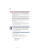
Modem On Hold Using Modem On Hold 2 21 To answer an incoming call, click Answer, then pick up your telephone handset. The Call Status box indicates that the Internet connection is on hold while you complete your voice call. Sample Modem On Hold in progress dialog box 3 To maintain the Internet connection, you must complete the voice call before the Modem On Hold timer expires. The application displays the timer in the lower right corner. The timeout value is determined by your ISP.
Modem On Hold Using Modem On Hold Sample Resuming modem connection dialog box The modem connection is automatically renegotiated and your Internet connection resumes. NOTE: A “Call Canceled” message may display. If this occurs, wait a few seconds while the modem automatically redials and reestablishes your Internet connection. Placing an outgoing voice call To use this function, your phone line must support three-way calling service.
Modem On Hold Using Modem On Hold 23 The V.92 Modem On Hold dialog appears, instructing you to click the Call button. Sample Placing a voice call dialog box 3 Before the 15-second timer runs out, click Call. Otherwise, click Ignore to cancel the call. The Call Status box indicates that the Internet connection is on hold while you complete your voice call. Sample Modem On Hold in progress dialog box 4 Pick up your telephone handset and place your voice call.
Modem On Hold Using Modem On Hold 6 To end your voice call and resume your Internet connection, wait until the incoming caller has hung up, then click Resume Data Call. If you hang up before the incoming caller, a “Call Cancelled” message may display. If this occurs, wait a few seconds while the modem automatically redials and reestablishes your Internet connection. A dialog displays, indicating that the Modem On Hold has been cancelled and instructing you to hang up.
Modem On Hold Configuring Modem On Hold 25 Viewing Call History The Modem On Hold application provides a log of the last ten incoming calls. The log includes the date, time, phone number, and Caller ID (if you have Caller ID service). 1 To view the call history, right-click the icon, located on the system tray, to display the modem popup window. Sample modem popup window 2 Click Call History to display the Call History log.
Modem On Hold Configuring Modem On Hold Configuring Modem On Hold settings You configure Modem On Hold settings from the V.92 MoH Settings dialog. 1 To open the V.92 MoH Settings dialog, double-click the icon, located on the system tray in the lower-right corner of your desktop. The V.92 MoH Settings dialog appears. Sample V.92 MoH Settings dialog box 2 If you do not have Call Waiting service, clear the Enable Call Waiting check box. All of the other settings in this dialog become unavailable.
Modem On Hold Configuring Modem On Hold 3 27 If you do not want the Modem On Hold feature enabled, select Disconnect call. Switch to voice. When the modem detects an incoming voice call during an Internet connection, it disconnects the Internet connection so that you can answer the voice call. 4 If Modem On Hold is enabled, you can select or clear the Enable Caller ID check box to match your telephone service.
Modem On Hold Configuring Modem On Hold Enabling/Disabling the Modem On Hold autorun status 1 Right-click the icon, located on the system tray, to display the modem popup window. Sample modem popup window 2 If Start Automatically is checked, you can click it to clear the check mark. The Modem On Hold application no longer launches automatically when you start your computer. 3 If Start Automatically is not checked, you can click it to select this option. A check mark appears next to the option.
Modem On Hold Locating the Modem On Hold application version 29 Removing the icon 1 Right-click the icon, located on the system tray, to display the modem popup window. Sample modem popup window 2 Click Exit MOH. A confirmation dialog appears. 3 Click OK to remove the icon from the system tray. Adding the icon From your desktop, click Start, Programs, Toshiba Internal Modem, Modem on Hold. The icon is added to the system tray.
Modem On Hold Locating the Modem On Hold application version 2 Click About MOH to display the application version. Sample About MOH 5.375 x 8.375 ver 2.4.
Chapter 2 Function Check This chapter describes how to check the internal modem’s functions. Use this procedure when the modem is not working properly, to help identify the problem and, in many cases, the solution. Running diagnostics If the modem is not working properly, running some simple diagnostics can help you determine if the modem drivers are installed correctly, or if the modem is not working due to a conflict with another application using the communications port.
Function Check Running diagnostics Sample Control Panel 2 Double-click Phone and Modem Options to open the Phone and Modem Options window. 5.375 x 8.375 ver 2.4.
Function Check Running diagnostics 33 Sample Phone and Modem Options window 3 Click the Modems tab to display the installed modems. 5.375 x 8.375 ver 2.4.
Function Check Running diagnostics Sample Modems tab dialog box 4 If it is not already selected, click Toshiba Software Modem, then click Properties to open the Toshiba Software Modem Properties window. 5.375 x 8.375 ver 2.4.
Function Check Running diagnostics Sample Toshiba Software Modem Properties window 5 Click the Diagnostics tab. 5.375 x 8.375 ver 2.4.
Function Check Running diagnostics Sample Diagnostics tab 6 Click Query Modem. The system executes an automatic operations test, displaying the following message while the test is in progress. Sample Diagnostics test in progress message If the diagnostic test runs successfully, a series of commands and the modem’s response displays in the Modem Information box. The modem drivers are installed correctly. 5.375 x 8.375 ver 2.4.
Function Check Running diagnostics 37 Sample Diagnostics results If the diagnostics test fails, you may see a “Can’t Open Port” message. This indicates that another application is using the COM port, or the modem driver is not properly installed. 7 If the diagnostic test fails, and this is the first time you’ve run the test, restart the computer and repeat step 1 through step 6.
Function Check Determining current connection protocol 12 Reinstall the Toshiba Software Modem driver. If you do not have the latest driver, you can download it from www.toshiba.com. 13 Repeat step 1 through step 6 to run diagnostics again. The issued AT commands, and the modem’s response, appear in the Modem Information box. Use the scroll bar, if necessary, to locate the ATI3 command and its response. 14 Verify that the driver you installed in step 12 is the currently installed driver.
Function Check Determining current connection protocol 39 Sample Control Panel 2 Double-click Phone and Modem Options to open the Phone and Modem Options window. 5.375 x 8.375 ver 2.4.
Function Check Determining current connection protocol Sample Phone and Modem Options window 3 Click the Modems tab to display the installed modems. 5.375 x 8.375 ver 2.4.
Function Check Determining current connection protocol Sample Modems tab 4 If it is not already selected, click Toshiba Software Modem, then click Properties to open the Toshiba Software Modem Properties window. 5.375 x 8.375 ver 2.4.
Function Check Determining current connection protocol Sample Toshiba Software Modem Properties window 5 Click the Diagnostics tab. 5.375 x 8.375 ver 2.4.
Function Check Determining current connection protocol 43 Sample Diagnostics tab 6 Click View log to display connection information about the last call. 7 Locate the data compression format in the log. If it lists V.44 data compression, the connection was a V.92 connection. 8 To append connection information for future calls to the existing call log, on the Diagnostics tab select the Append to Log check box. 5.375 x 8.375 ver 2.4.
Chapter 3 Using the Internal Modem This chapter describes connection procedures and basic operations. Connection procedures This section describes how to connect the internal modem to, and disconnect it from, a telephone jack. CAUTION: The modem is designed for use with a standard analog telephone line. Do not connect the modem to a digital telephone line. A digital line may damage the modem.
Using the Internal Modem Connection procedures 45 Analog or digital? ❖ If you are not sure which type of line a particular line jack offers, assume that it is digital and do not connect the internal modem to it. ❖ If the wall jack is known to be connected to a PBX (Private Branch Exchange) system, then the line is digital. Do not connect the modem to it. ❖ If a (working) telephone connected to the wall jack has an REN (Ringer Equivalency Number) printed on its label, then it is an analog phone.
Using the Internal Modem Connection procedures Connecting the internal modem NOTE: When you connect the RJ11 jack, insert it until you hear a click. Disconnecting the internal modem When you need to disconnect the internal modem’s modular cable: 1 Pinch the connecting lever on the connector in the telephone wall jack and pull out the connector. Squeeze here Disconnecting the cable from the wall jack 2 Disconnect the modular cable from the computer’s modem port. 5.375 x 8.375 ver 2.4.
Using the Internal Modem Basic operation 47 Basic operation After you connect the modular cable to your internal modem and a telephone line, you are ready to run your communication software. Refer to your software documentation for instructions on operating your internal modem. As examples, this section describes how to execute basic modem operations by typing AT commands directly into the communication software program. You must be in terminal mode to enter the AT commands.
Using the Internal Modem Basic operation Extension line If you are calling from an extension line, such as in an office building, and need to dial nine or another number to gain external access, follow the steps below. ❖ To place a call using tone dialing, enter: ATDT 9, ******* and press Enter. The nine or other number is for line access; the comma (,) is for a pause (about 2 seconds with the default setting) to give time for a connection. The asterisks * indicate the number you are calling.
Using the Internal Modem Basic operation 49 Receiving a call To set the number of rings before the internal modem automatically answers the phone, set the S0 register as follows: ATS0=* and press Enter. The asterisk * indicates the number of rings. See “S-Register values” on page 82 for more details. Terminating a call The methods for terminating a call depend on the status of the connection. ❖ If the internal modem is dialing or has not yet gone online, you can terminate a call by pressing any key.
Using the Internal Modem Basic operation CTS/RTS control This control method is hardware-dependent. To control data flow, the modem and computer transmit Clear To Send/ Request To Send signals to each other. To set CTS/RTS control, enter the following AT command: AT\Q3 XON/XOFF control This control method is managed by software. The start/stop signals, that is transfer on/transfer off, are included in the data stream.
Chapter 4 AT Commands In most cases, you will not need to type AT commands manually. However, there may be some occasions when you will need to do so. This chapter describes AT commands for data mode. Fax commands are issued by application software. AT command formats The format for entering AT commands is: ATXn where X is the AT command, and n is the specific value for some of the commands. After you type in the command, press Enter.
AT Commands AT command formats +++ Escape sequence The escape sequence allows the modem to exit data mode and enter online command mode. While in online command mode, you can communicate directly with your modem using AT commands. When you finish, you can return to data mode using the ATO command. There must be a pause after you enter an escape sequence before any additional characters can be sent to the modem. The length of this pause is set by Escape Guard Time (S12).
AT Commands AT command formats 53 B1 Selects Bell 212A when the modem is at 1200 bps. B2 Unselects V.23 reverse channel. B3 Unselects V.23 reverse channel. B15 Selects V.21 when the modem is at 300 bps. B16 Selects Bell 103J when the modem is at 300 bps. Result Codes: OK n = 0,1,2,3,15,16 ERROR Otherwise Dn Dial This command instructs the modem to dial a telephone number. Enter n (the telephone number and any modifiers) after the ATD command.
AT Commands AT command formats @ Wait for quiet answer. Wait for five seconds of silence after dialing the number. If silence is not detected, the modem sends a NO ANSWER result code back to the caller. ! Hook flash. Causes the modem to go on-hook for 0.5 seconds and then return to off-hook. ; Return to command mode. Causes the modem to return to command mode after dialing a number, without disconnecting the call. L Redials last number.
AT Commands AT command formats 55 Hn Hook control This command instructs the modem to go on-hook to disconnect a call, or off-hook to make the phone line busy. H0 Modem goes on-hook (default). H1 Modem goes off-hook. Result Codes: OK n=0,1 ERROR Otherwise In Request ID information This command displays product information about the modem. I0 or I3 Returns the modem identity string and driver version number. I1 Returns OK (no function). I2 Returns OK (no function).
AT Commands AT command formats The following table contains an example of the connection information returned by the I11 command: Description Status Last Connection V.92 Initial Transmit Carrier Rate 24000 Initial Receive Carrier Rate 49333 Final Transmit Carrier Rate 24000 Final Receive Carrier rate 49333 Protocol Negotiation Result LAPM Data Compression Result V.
AT Commands AT command formats Connection Time (sec) 57 19.968 OK The ATI11 command may be issued from online command mode or after the end of a call. After a call, some of the values are no longer valid. The following table defines each command result, and indicates if the result is valid only during the call: Description Definition Last Connection V.92, V.90, V.34, or V.32, depending on the type of connection negotiated. Initial Transmit Carrier Rate Initial upstream rate.
AT Commands AT command formats Transmit Signal Power Level (-dBm) The signal power transmitted upstream. Round Trip Delay The round trip delay, in (msec) milliseconds. Near Echo Level (-dBm) Near echo levels only. Far Echo level (-dBm) Far echo levels only. Transmit Frame Count The number of LAPM frames sent upstream during this call. The count wraps around at 65,535. Transmit Frame Error Count The number of REJ frames received at the analog client modem.
AT Commands AT command formats Call Termination Cause Robbed-Bit Signaling 59 The reason the call ended. This value is valid only after the call ends. 0 local modem command; ATH, DTR drop. 1 remote modem command: cleardown, loss of signal. 2 no answer, busy, etc. 3 training failure (V.90 or V.34). 4 protocol failure, for example if required by \N4. For PCM connection only, a hexadecimal 6-bit pattern of T1 frames with robbed-bit signaling.
AT Commands AT command formats Ln Monitor speaker volume This command sets speaker volume to low, medium, or high. L0 Low volume L1 Low volume (Same as L0) L2 Medium volume (default) L3 High volume Result Codes: OK n=0,1,2,3 ERROR Otherwise Mn Monitor speaker mode This command turns the speaker on or off. M0 The speaker is off. M1 The speaker is on until the modem detects the carrier signal (default). M2 The speaker is always on when modem is offhook.
AT Commands AT command formats 61 Nn Modulation handshake This command controls whether or not the local modem performs a negotiated handshake at connection time with the remote modem when the communication speed of the two modems is different. N0 When originating or answering, this is for handshake only at the communication standard specified by S37 and the ATB command. N1 When originating or answering, begin the handshake at the communication standard specified by S37 and the ATB command (default).
AT Commands AT command formats P Select pulse dialing This command configures the modem for pulse (non-touchtone) dialing. Dialed digits are pulsed until a T command or dial modifier is received. Tone dial is the default setting. Qn Result code control Result codes are informational messages sent from the modem and displayed on your monitor. Basic result codes are OK, CONNECT, RING, NO CARRIER, and ERROR. The ATQ command allows the user to turn result codes on or off.
AT Commands AT command formats 63 Result Codes: OK n=0,1 ERROR Otherwise Wn Result Code Option W0 CONNECT result code reports DTE speed. Disable protocol result codes. W1 CONNECT result code reports DTE speed. Enable protocol result codes. W2 CONNECT result code reports DCE speed. Enable protocol result codes (default).
AT Commands AT command formats Extended result codes Disabled: Displays only the basic result codes: OK, CONNECT, RING, NO CARRIER, and ERROR. Enabled: Displays basic result codes, along with the connect message and the modem’s data rate, and an indication of the modem’s error correction and data compression operation. Dial tone detect Disabled: The modem dials a call regardless of whether it detects a dial tone.
AT Commands AT command formats 65 Zn Recall stored profile The modem performs a soft reset and restores (recalls) a configuration profile according to the parameter supplied. You can store two configuration profiles. If no parameter is specified, zero is assumed. Z0 Reset and restore stored profile 0. Z1 Reset and restore stored profile 1.
AT Commands AT command formats &Dn Data Terminal Ready (DTR) control This command interprets how the modem responds to the state of the DTR signal and changes to the DTR signal. &D0 Ignore. The modem ignores the true status of DTR and treats it as always on. This should only be used if your communication software does not provide DTR to the modem. &D1 If the DTR signal is not detected while in online data mode, the modem enters command mode, issues an OK result code, and remains connected.
AT Commands AT command formats 67 &Gn V.22bis guard tone control This command determines which guard tone, if any, to transmit while transmitting in the high band (answer mode). This command is only used in V.22 and V.22bis mode. This option is not used from North America and is for international use only. &G0 Guard tone disabled (default). &G1 Sets guard tone to 550 Hz. &G2 Sets guard tone to 1800 Hz.
AT Commands AT command formats &Pn Select Pulse Dial Make/Break Ratio &P0 Selects 39% - 61% make/break ratio at 10 pulses per second. &P1 Selects 33% - 67% make/break ratio at 10 pulses per second. &P2 Selects 33% - 67% make/break ratio at 20 pulses per second. Result Codes: OK n=0 to 2 ERROR Otherwise &Tn Self-test commands These tests can help to isolate problems if you experience periodic data loss or random errors. &T0 Abort. Stops any test in progress.
AT Commands AT command formats 69 &V View active configuration and stored profile The modem maintains two stored profiles, in addition to the active profile. This command is used to display all three modem configurations, and any stored telephone numbers. &V View all three configurations and any stored telephone numbers. &W Store current configuration This command saves the current (active) configuration (profile), including all S-Registers except S3, S4 and S5.
AT Commands AT command formats &Zn=x Store telephone number This command is used to store up to four dialing strings in the modem’s nonvolatile memory for later dialing. The format for the command is &Zn=“stored number” where n is the location 0-3 to which the number should be written. The dial string may contain up to 34 characters. The ATDS=n command dials using the string stored in location n.
AT Commands AT command formats \N7 71 V.42. MNP or Buffer (same as \N3). Result Codes: OK n = 0,1,2,3,4,5,7 ERROR Otherwise Qn Local flow control selection \Q0 Disable flow control. \Q1 XON/XOFF software flow control. \Q3 RTS/CTS to DTE (default). Result Codes: OK n = 0,1,3 ERROR Otherwise \Vn Protocol result code \V0 Disable protocol result code appended to DCE speed. \V1 Enable protocol result code appended to DCE speed (default). Result Codes OK n = 0,1 ERROR Otherwise 5.
AT Commands AT command formats %Cn Data compression control This command determines the operation of V.42bis and MNP class 5 data compression. Online changes do not take effect until a disconnect occurs first. %C0 V.42bis/MNP 5 disabled. No data compression. %C1 V.42bis/MNP 5 enabled. Data compression enabled (default). Result Codes: OK n = 0, 1 ERROR Otherwise -V.90= This command enables/disables V.90 and changes the downstream rate. -V90=0 Disables V.90 -V90=1 Enables V.
AT Commands AT command formats 5 32000 bps 6 33333 bps 7 34666 bps 8 36000 bps 9 37333 bps 10 38666 bps 11 40000 bps 12 41333 bps 13 42666 bps 14 44000 bps 15 45333 bps 16 46666 bps 17 48000 bps 18 49333 bps 19 50666 bps 20 52000 bps 21 53333 bps 73 +DS44 V.44 Data Compression Command This command configures the V.44 data compression direction used by the modem.
AT Commands AT command formats 1 Modem negotiates V.44 compression for transmit only. 2 Modem negotiates V.44 compression for receive only. 3 Modem accepts V.44 compression in both or either direction (default). Result Codes: OK = 0,1,2,3 ERROR Otherwise +DS44? This command displays the current V.44 compression configuration. +DS44=? This command displays the supported +DS44 parameter values.
AT Commands AT command formats 75 This command is used to set the various parameters described below: The modem protocol. Valid values are: Value Meaning V92 V90 V34 V32T V32B V32 V22B V22 Bell212A V23C V.92 (default) V.90 V.34 V.32ter V.32bis V.32 V.22bis V.22 Bell 212A V.23, constant carrier, asymmetric FDM V.
AT Commands AT command formats The maximum receive rate. If set to 0, then the max rate will be determined by the modulation means selected in the and settings. Zero is the default. Valid values are from 300 to 57333. Maximum receive rates for each valid are as follows, in bits per second: V92 V90 V34 V32B V32 V22bis V22 Bell212A V23C V.
AT Commands AT command formats 77 +PCW Command This command configures how the modem responds to a call waiting signal. The modem’s response is also determined by the current configuration of the +VCID caller ID command (See “+VCID Command” on page 79 for information on this command). You can also use the +PCW command to display the current call waiting configuration, and to display the supported parameter values.
AT Commands AT command formats +PIG Command This command enables or disables PCM upstream. You can also use this command to display the current PCM upstream configuration, and to display the supported +PIG command parameter values. +PIG= Valid parameter values are as follows: 0 Enables PCM upstream. 1 Disables PCM upstream. This is the default. Result Codes: OK = 0,1 ERROR Otherwise +PIG? This command displays the current +PIG command configuration.
AT Commands AT command formats 79 +PMH Command This command enables or disables the Modem On Hold feature. You can also use this command to display the current Modem on Hold configuration, and to display the supported +PMH command parameter values. +PMH= Valid parameter values are as follows: 0 Enables Modem On Hold. This is the default. 1 Disables Modem on Hold. Result Codes: OK = 0,1 ERROR Otherwise +PMH? This command displays the current +PMH command configuration.
AT Commands AT command formats +VCID= Valid parameter values are as follows: 0 Disables caller ID. This is the default. 1 Enables caller ID, with formatted presentation. 2 Enables caller ID, without formatting. Result Codes: OK = 0,1,2 ERROR Otherwise +VCID? This command displays the current caller ID configuration. +VCID=? This command displays the supported +VCID parameter values. 5.375 x 8.375 ver 2.4.
Chapter 5 S-Registers S-Registers contain the settings that determine how several functions of the internal modem operate, such as choosing how many times to let the telephone ring before the modem answers and how long to wait before it hangs up if a connection fails. You can also customize certain AT commands, such as the escape sequence and command line termination. The contents of the registers are changed automatically when you modify corresponding settings in your communication software.
S-Registers S-Register values S-Register values ❖ The format for displaying the value of an S-Register is: ATSn? where n is the register number. After you type in the register press Enter. ❖ The format for modifying the value of an S-Register is: ATSn=r where n is the register number, and r is the new register value. After you type in the register number and its new value press Enter.
S-Registers S-Register values 83 S2 AT escape character (user-defined) This register determines the ASCII value used for an escape sequence. The default is the + character. The escape sequence allows the modem to exit data mode and enter command mode when online. Values greater than 127 disable the escape sequence. Range: 0-255 Default: 43 Units: ASCII S3 Command line termination character (user-defined) This register determines the ASCII values as the carriage return character.
S-Registers S-Register values S5 Command line editing character (user defined) This register sets the character recognized as a backspace and pertains to asynchronous transmission only. The modem will not recognize the backspace character if it is set to an ASCII value greater than 32. This character can be used to edit a command line. When the echo command is enabled, the modem echoes back to the local DTE the backspace character, an ASCII space character, and a second backspace character.
S-Registers S-Register values 85 S7 Connection completion time-out This register sets the time, in seconds, that the modem must wait before hanging up because the carrier is not detected. The timer is started when the modem finishes dialing (originate), or goes off-hook (answer). In originate mode, the timer is reset upon detection of an answer tone if allowed by county restriction. The timer also specifies the wait for silence time for the @ dial modifier in seconds.
S-Registers S-Register values S12 Escape guard time This register sets the value (in 20 ms increments) for the required pause after the escape sequence (default 1 second). Range: 0-255 Default: 50 Units: .
S-Registers AT command set result codes 87 AT command set result codes The following table shows the result codes: Command Set Result Codes Table Result Code Numeric Description OK 0 Command executed CONNECT 1 Modem connected to line RING 2 A ring signal has been detected NO CARRIER 3 Modem lost carrier signal, or does not detect carrier signal, or does not detect answer tone ERROR 4 Invalid command CONNECT 1200 EC* 5 Connection at 1200 bps NO DIAL TONE 6 No dial tone detected BUSY
S-Registers AT command set result codes Command Set Result Codes Table (Continued) Result Code Numeric CONNECT 9600 EC* Description 12 Connection at 9600 bps CONNECT 14400 EC * 13 Connection at 14400 bps CONNECT 19200 EC * 14 Connection at 19200 bps 24 Connection at 7200 bps CONNECT 12000 EC* 25 Connection at 12000 bps * 86 Connection at 16800 bps CONNECT 7200 EC * CONNECT 16800 EC CONNECT 300 EC * 40 Connection at 300 bps * 55 Connection at 21600 bps CONNECT 24000 EC* 5
S-Registers AT command set result codes 89 Command Set Result Codes Table (Continued) Result Code Numeric Description CONNECT 57600 EC* 18 Connection at 57600 bps (DTE rate) CONNECT 115200 EC* 87 Connection at 115200 bps (DTE rate) CONNECT 32000 EC* 70 Connection at 32000 bps * 71 Connection at 34000 bps CONNECT 36000 EC* 72 Connection at 36000 bps CONNECT 38000 EC * 73 Connection at 38000 bps CONNECT 40000 EC * 74 Connection at 40000 bps CONNECT 42000 EC * 75 Connection at 42
S-Registers AT command set result codes Command Set Result Codes Table (Continued) Result Code Numeric Description CONNECT 56000 EC* 82 Connection at 56000 bps CONNECT 28000 EC* 100 Connection at 28000 bps CONNECT 29333 EC* 101 Connection at 29333 bps CONNECT 30666 EC* 102 Connection at 30666 bps CONNECT 33333 EC* 103 Connection at 33333 bps CONNECT 34666 EC* 104 Connection at 34666 bps CONNECT 37333 EC* 105 Connection at 37333 bps CONNECT 38666 EC* 106 Connection at 38666 bps
S-Registers AT command set result codes 91 Command Set Result Codes Table (Continued) Result Code Numeric CONNECT 54666 EC* 114 Description Connection at 54666 bps * EC appears only when the Extended Result Codes configuration option is enabled. EC is replaced by one of the following symbols, depending upon the error control method used: V.44 - V.44 data compression with V.42 error control V.42bis - V.42 error control and V.42bis data compression V.42 - V.
Chapter 6 Test Function Normally, data communications are executed by connecting your computer and modem to those of a remote station with a communication line. If any errors or malfunctions are encountered, it is necessary to check whether the cause is in the local station, the remote station or the communication line. Test description This internal modem has a local/analog/loopback test function that identifies the cause of a malfunction.
Test Function Testing procedure 93 Modem Computer Transmission Reception Transmitter Receiver Local/analog/loopback test Testing procedure To conduct the loopback test: 1 Enter the following AT commands to set the modem to normal mode: AT&F\N0 Receive OK 2 Enter the following AT commands to select the local/ analog/loopback test: AT&T1 You are now in the online state. 3 Enter characters from the keyboard as desired. The characters you enter should be displayed on the screen. 5.375 x 8.
Test Function Testing procedure 4 Enter the escape code as follows to return to the command state from the online state. +++ Receive OK. 5 Enter the following AT commands to terminate the test: AT&T0 Receive OK. 5.375 x 8.375 ver 2.4.
Chapter 7 MNP and V.42 2 The internal modem has built-in protocols MNP (Microcom Networking Protocol) Class 4 and V.42 for error correction and MNP class 5 and V.42bis for data compression. Error-correction overview Telephone line noise, or electrical interference, can cause errors in data communication. Noise is especially a problem at high speeds of 14,400 bps or greater. The MNP and V.
MNP and V.42 Operation modes The protocol of both modems must be the same. Therefore, if the remote modem supports only class 3 or below, the protocol for the remote modem will be used. If the remote modem does not use MNP, the communication will be made at the speed of the remote modem. V.42 error correction The V.42 (ITU-T-Rec V.42) protocol is recommended by the ITU (International Telecommunications Union). V.
MNP and V.42 Flow control 97 Commands (\ Nn) The following N modulation handshake commands are used to set the communication mode: \N0, \N1 Remote modem unable to use MNP or V.42 \N2 Remote modem uses MNP \N3 Uncertain if remote modem can use MNP or V.42 \N4 Remote modem uses V.42 \N5, \N7 Same as \N3 For details, refer to “AT Commands” on page 51.
MNP and V.42 Flow control Computer Modem DTE Transmit Receive Buffer DCE Phone line Phone Circuit Buffer Serial port flow control Modem port flow control Flow control Serial port flow control Serial port data flow is controlled by the modem in its communication with a personal computer. If the serial port speed is higher than the modem port speed, this control function sends a transmission halt request to the personal computer before the buffers in the modem are about to become full.
MNP and V.42 Flow control 99 Since these two codes, XON and XOFF, are used as flow control characters, binary data that includes these two codes cannot be transmitted or received. CTS/RTS two-way flow control (hardware) Flow control is performed by turning on and off the control lines CTS (clear to send) and RTS (request to send) between the modem and the computer. A transmission halt or restart request is made from the modem to the computer using the CTS signal.
MNP and V.42 Data compression Modem port flow control Modem port flow control refers to flow control between the modems of the local station and remote station. If data transmission from the modem under serial port flow control is interrupted because the computer cannot catch up with it, modem port flow control is applied to the remote modem so that transmitted data will not exceed buffer capacity. This flow control functions in normal mode only. Data compression Protocols MNP class 5 and V.
Appendix A Specifications This appendix summarizes the Toshiba internal modem’s technical specifications. Network control unit (NCU) Type of NCU AA Type of line General telephone line Type of dialing Pulse Tone Control command AT commands EIA-578 commands Monitor function Computer’s speaker 101 5.375 x 8.375 ver 2.4.
Specifications Communication specifications Communication specifications Communication system Data: Full duplex Fax: Half duplex Communication protocol Data: ITU-T-Rec V.21 / V.22 / V.22bis / V.32 / V.32bis / V.34 / 56K /V.90 / V.92 Bell 103/212A Fax: ITU-T-Rec V.17 / V.29 / V.27ter (Former CCITT) ch2 Communication speed /V.
Appendix B Communication Conditions Communication parameters Select communication parameters from the table below. Start (bit) Data length (bit) Parity (bit) Stop (bit) 1 8 None 1 or more 1 7 0 1 or more 1 7 1 1 or more 1 7 Odd 1 or more 1 7 Even 1 or more 1 7 None 2 Telephone line types This internal modem can be connected to 2-wire analog subscriber telephone lines (POTS lines) only. 103 5.375 x 8.375 ver 2.4.
Communication Conditions Dial modes Connectable lines (2-wire) ❖ Ordinary analog telephone lines with direct connection ❖ Corporate analog lines connected to a PBX ❖ Analog lines connected to a PBX, which, for example, provide dial tone when the handset is picked up and permit outgoing calls by dialing 9. Unconnectable lines (4-wire) ❖ Business or home telephones that are connected to a key service unit or a PBX. WARNING: These are digital lines that can damage the modem.
Glossary Acronyms bps or BPS:Bits per Second COM1: Communications Port 1 (serial port) COM2: Communications Port 2 (serial port) CPU: Central Processing Unit FCC: Federal Communications Commission FTP: File Transfer Protocol GND: Ground HDD: Hard Disk Drive HTML: HyperText Markup Language I/O: Input/Output IRQ: Interrupt Request ISA: Industry Standard Architecture KB: Kilobyte LAN: Local Area Network LBA: Logical Block Addressing 105 5.375 x 8.375 ver 2.4.
Glossary LFB: Linear Frame Buffer LPT1: Line Printer Port 1 (parallel port) MB: Megabyte MIPS: Millions of Instructions per Second PBX: Private Branch Exchange PCI: Peripheral Component Interconnect PIO: Programmed Input/Output RFI: Radio Frequency Interference ROM: Read-Only Memory RTC: Real-Time Clock SIMM: Single Inline Memory Module SPB: Synchronous Pipeline Burst (cache) UART: Universal Asynchronous Receiver/Transmitter URL: Universal Resource Locator USB: Universal Serial Bus VCR: Video Cassette
Glossary 107 American National Standards Institute (ANSI) character set: The set of characters available in Microsoft® Windows® operating system (or other operating system). The character set includes letters, numbers, symbols and foreign language characters. American Standard Code for Information Interchange (ASCII): A set of 256 binary codes that represent the most commonly used letters, numbers and symbols. See also binary.
Glossary bits per second (BPS): A way of measuring the speed at which information is passed between two devices. This is the basic measure used in modem communications. This is similar, but not identical, to the baud rate. See also baud. buffer: An area of memory where information is held until it can be processed. Buffers are frequently used to compensate for the fact that some parts of the system are faster than others.
Glossary 109 character: Any letter, number or symbol you can use on the computer. Some characters are non-printing characters, such as a paragraph break in a word-processing program. A character occupies one byte of computer storage. Class 1: A standard for fax transmission. The Toshiba internal modem supports class 1. choose: To use the mouse or keyboard to select a menu item, a button or an icon. click: To press and release a mouse button.
D Glossary DAA: Data Access Arrangement is a circuit that isolates a device from phone lines. data: Information that a computer can process. The word “data” is actually plural for “datum,” meaning a single piece of information. data bits: A data communications parameter controlling the number of bits used to represent a character. If data bits = 7, the computer can generate 128 unique characters, if data bits = 8, the computer can generate 256 unique characters.
Glossary 111 DSR signal: This signal tells the personal computer whether the modem is ready for communication. DTR signal: This signal tells the modem whether the personal computer is ready for communication. duplex: The method used to transmit data in both directions between two devices. Synonymous with full duplex. See also half duplex, full duplex. E echo: Displays keyboard entry on the computer terminal.
Glossary Flow control: Flow control ensures smooth data communication. If operating speed differs between the personal computer and modem or between your modem and a remote modem and if the remote station runs short of buffer capacity, a transmission halt request is sent from the receiver to the transmitter. When the receiver has enough buffer capacity to resume receiving data, a transmission restart request is sent.
Glossary 113 input/output (I/O): Input and output are two of the three functions that computers perform (the other is processing). Input/Output describes the interrelated tasks of providing information to the computer and providing the results of processing to users. I/O devices include keyboards (input) and printers (output). A disk drive is both an input and an output device, since it can both provide information to the computer and receive information from the computer.
Glossary N Normal mode: Error correction is not made by MNP or V.42, but even if serial port speed is different from modem port speed, the buffers in the modem and its flow control function permit communication without changing their speeds. O on line: A functional state in which a device is ready to receive or transmit information. online: Available through the computer.
Glossary 115 Pulse dialing: A dialing method that uses pulses instead of tones to generate a telephone number. Generally associated with rotary dial phones, although some push-button phones can be used on pulse lines. R Reliable mode: Reliable mode is for error-free communication by MNP or V.42. Result code: This code returns to the computer the results of executing a command sent from it to the internal modem in characters or numeric values.
Glossary synchronous: Having a constant time interval between successive bits, characters or events. Synchronous data transmission requires both the sending and receiving devices to use special synchronizing characters to correct variations in timing between the devices. See also asynchronous. T Test function: When normal communication is not possible, this function checks the modem, personal computer, and telephone lines to determine if they are normal.
Index Numerics 56K technology 16 A analog/loopback test 92 answering a call 20 AT command 52 AT command set result codes 87 AT commands answer command 52 Call Waiting 77 Caller ID enable/disable 79 communication standard setting 52 data carrier detect 65 data compression control 72 data terminal ready (DTR) 66 dial a telephone number 53 dial tone detect 64 display result codes 62 echo command 54 error control mode selection 70 escape sequence 52 extended result codes 64 format 51 guard tone control 67 hoo
Index select stored profile for hardware reset 69 select tone dialing 62 self-test commands 68 store current configuration 69 store telephone number 70 V.44 data compression 73 V.
Index hook control 55 N I N modulation handshake 61 icons definitions 14 internal modem communications protocols 17 connecting 45 connection procedures 44 disconnecting 46 O L load factory settings 66 local flow control selection 67, 71 loopback test 93 M MNP protocol 95 modem connecting internal 44 flow control function 97 modem port 97 serial port 97 maximum connection speed 74 protocol settings 74 protocols 16 Modem On Hold 14 answering a call 20 application 19 AT command 79 autorun 28 configurin
Index S-register values AT escape character 83 Comma pause time 85 Command line editing character 84 Command line termination character 83 Connection completion time-out 85 Dial line rate 86 DTMF dialing speed 85 Escape guard time 86 Response formatting character 83 Wait before dialing 84 store current configuration 69 store telephone number 70 T telephone line connecting to 47 direct access line 47 extension line 48 terminating a call 49 test description 92 function 92 methods 92 test function loopb