AW5500 Industrial Wireless Access Point User’s Manual v.1.
Atop Industrial Wireless Access Point AW5500 User Manual V. 1.3 Important Announcement The information contained in this document is the property of Atop Technologies, Inc., and is supplied for the sole purpose of operation and maintenance of Atop Technologies, Inc. products.
Atop Industrial Wireless Access Point AW5500 User Manual V. 1.3 Contents 1 Preface ..................................................................................................... 1 2 Introduction.............................................................................................. 5 3 4 2.1 Product Overview ......................................................................................................5 2.2 Features ..............................................................
Atop Industrial Wireless Access Point AW5500 User Manual V. 1.3 4.9.4 IP Filtering ...................................................................................................... 53 4.9.5 Management List ........................................................................................... 54 4.10 System Log ............................................................................................................. 55 4.10.1 Syslog ..........................................................
Atop Industrial Wireless Access Point AW5500 User Manual V. 1.3 8 System Recovery................................................................................... 97 9 Warranty .................................................................................................
Atop Industrial Wireless Access Point AW5500 User Manual V. 1.3 1 Preface Purpose of the Manual This manual supports you during the installation and configuring of the AW5500 Industrial Wireless Access Point only, as well as it explains some technical options available with the mentioned product.
Atop Industrial Wireless Access Point AW5500 User Manual V. 1.3 Manufacturers Federal Communication Commission Declaration of Conformity Statement Model: AW5500 NOTE: This equipment has been tested and found to comply with the limits for a Class A digital device, pursuant to Part 15 of the FCC Rules. These limits are designed to provide reasonable protection against harmful interference when the equipment is operated in a commercial environment.
Atop Industrial Wireless Access Point AW5500 User Manual V. 1.3 European Community, Switzerland, Norway, Iceland, and Liechtenstein Model: AW5500 Declaration of Conformity with regard to the R&TTE Directive 1999/5/EC This equipment is in compliance with the essential requirements and other relevant provisions of 1999/5/EC. The following standards were applied: EMC EN 301.489-1 v1.4.1; EN 301.489-17 v1.2.1 Health & Safety EN60950-1: 2001; EN 50385: 2002 Radio EN 300 328 v 1.7.1; EN 301.893 v 1.5.
Atop Industrial Wireless Access Point AW5500 User Manual V. 1.3 Caution Beginning from here there will be extreme caution exercised. Never install or work on electrical cabling during periods of lightning activity. Never connect or disconnect power when hazardous gases are present WARNING: Disconnect the power and allow to cool 5 minutes before touching.
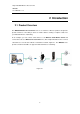
Atop Industrial Wireless Access Point AW5500 User Manual V. 1.3 2 Introduction 2.1 Product Overview The AW5500 Wireless Access Point series is our new line of wireless products designed to provide a wireless connectivity to clients or mobile stations creating a complete solution for your industrial wireless networking.
Atop Industrial Wireless Access Point AW5500 User Manual V. 1.3 2.2 Features AW5500 is our latest addition to our Industrial Wireless products; its small size but powerful architecture makes it a perfect choice for industrial/manufacturing needs in which size is a decisive factor. It rewards our customers with superb connectivity. Among its many characteristics, we could mention: Stream input/output with maximum link speed of 300 Mbps and throughput of 100 Mps (environment dependent).
Atop Industrial Wireless Access Point AW5500 User Manual V. 1.3 3 Getting Started 3.1 Inside the Package Inside the product purchased you will find the following items: Table 3.
Atop Industrial Wireless Access Point AW5500 User Manual V. 1.3 3.2 Front & Power Panels The Front (Figure 3.1), and Power panels (Figure 3.2), are as follow: Figure 3.1 Figure 3.
Atop Industrial Wireless Access Point AW5500 User Manual V. 1.3 The Rear panel (where you can mount the device on a rail or to the wall), looks as in Figure 3.3, a simple mounting instruction is given on Figure 3.4. For more information on hardware installation, please refer to the product’s installation Guide. Figure 3.4 Figure 3.
Atop Industrial Wireless Access Point AW5500 User Manual V. 1.3 3.3 First Time Installation Before installing the device, please adhere to all safety procedures described below, Atop will not be held liable for any damages to property or personal injuries resulting from the installation or overall use of the device. Do not attempt to manipulate the product in any way if unsure of the steps described here, in such cases please contact your dealer immediately.
Atop Industrial Wireless Access Point AW5500 User Manual V. 1.3 3.4 Finding the Device As soon as the device is connected to the network, the user can search for its IP settings using Device View © , (utility that comes in the CD); as noted in Figure 3.5 below, important information such as the IP, MAC address, etc is going to be displayed. Figure 3.
Atop Industrial Wireless Access Point AW5500 User Manual V. 1.3 Figure 3.
Atop Industrial Wireless Access Point AW5500 User Manual V. 1.3 3.5 Factory Default Settings Upon arrival, the device will be set as Regular AP, the rest of the settings are as follow: Table 3.2 Mode Regular AP WDS Bridge AP Client Wireless Basic Settings AP Enabled AP1 SSID AW5500 SSID Broadcast Enabled Wireless Mode 802.11b/g/n Channel 1 (Automatic Channel Selection enabled) Bandwidth WDS Mode N.A. Auto 20/40 MHz N.A. Root AP Disabled N.A. Security Settings Security Mode N.A.
Atop Industrial Wireless Access Point AW5500 User Manual V. 1.3 Wireless Isolation 20/40 MHz Coexistence Disabled (Only be supported at 802.11n with 2.4 GHz) N.A. Enabled N.A. Mobile Station SSID AW5500 BSSID (MAC Address) Disabled WPS BUTTON Clickable Topology Infrastructure Band mode Bandwidth Auto Channel N.A.
Atop Industrial Wireless Access Point AW5500 User Manual V. 1.3 System Contact Contact System Location Location Read Community None (SNMP disabled) Write Community SNMP Trap Server 0.0.0.
Atop Industrial Wireless Access Point AW5500 User Manual V. 1.3 Syslog Server Service Port 514 System Setup Username admin Old Password New Password NULL (Blank) Repeat new password Web Mode HTTP Device name Device’s MAC Address NTP Disabled NTP Server pool.ntp.
Atop Industrial Wireless Access Point AW5500 User Manual V. 1.3 4 Web Console Configuration 4.1 Overview Information AW5500 is an Industrial Wireless solution for applications in harsh environments. The AW5500 is tough enough, expected to operate at temperatures ranging from -10°C~60°C. The ease of installation makes it attractive as it uses a DIN-Rail for fixing itself to virtually any surface in your workplace.
Atop Industrial Wireless Access Point AW5500 User Manual V. 1.3 right side of your screen the contents of each mode/option will be displayed in a graphical state. Since each Mode of operation is different, the content will differ, for more information on each selection please refer to each option’s Section throughout the manual. Figure 4.
Atop Industrial Wireless Access Point AW5500 User Manual V. 1.3 In general, there will be three buttons which will be present at the end of almost each configuration: Table 4.1 Button Function Saves the current configuration input on the page only, the configuration itself will not be applied to the device. We recommend users to use this button before the configuration process is completed and then press “Apply” at the last step. Save and apply the current configuration input on the page.
Atop Industrial Wireless Access Point AW5500 User Manual V. 1.3 2.4 GHz signaling standard. Although it performs much better than traditional dial-up networking, its performance is still significantly less than 802.11a and other, newer standards. 802.11g; very similar to 802.11b, the main difference being that it is done in a maximum raw data rate of 54 Mbps (20 Mbps net throughput), at the same 2.4 GHz bandwidth 802.
Atop Industrial Wireless Access Point AW5500 User Manual V. 1.3 The basic settings are explained in detail below: Radio On: AW5500 supports up to three multiple SSIDs (AP1, AP2, and AP3).AP1 must be enabled before you can proceed to AP2 and AP3. AP2 and AP3’s settings are only shown when they are enabled. When all three APs are disabled, wireless radio would turn off completely.
Atop Industrial Wireless Access Point AW5500 User Manual V. 1.3 Figure 4.
Atop Industrial Wireless Access Point AW5500 User Manual V. 1.3 Figure 4.5 SSID Broadcast: allow any wireless client to search for this access point presence, it is enabled by default. When the SSID Broadcast is disabled, wireless clients need to manually input the SSID in their wireless client configuration, increasing network security to prevent an access from unsolicited clients. Wireless Mode: The modes are separated into two parts by different colors.
Atop Industrial Wireless Access Point AW5500 User Manual V. 1.3 channels 1, 6, and 11 are the non-overlapping channels for 2.4 GHz Figure 4.6. Again, you can use “Scan network” to see which channels are already occupied. Bandwidth: when 40 MHz is used, AW5500 will double the channel width to 40 MHz as compared to the standard 20 MHz to transmit its data; this is not recommended for 802.11b/g/n since it will leave only one non-overlapping channel for other APs. HT40 (40 MHz), is recommended for 802.
Atop Industrial Wireless Access Point AW5500 User Manual V. 1.3 Figure 4.
Atop Industrial Wireless Access Point AW5500 User Manual V. 1.3 Table 4.3 20 MHz 2.4 GHz Primary channel Blocks 40MHz upper nd 2 ch. 40 MHz lower Center Blocks nd 2 ch.
Atop Industrial Wireless Access Point AW5500 User Manual V. 1.3 Table 4.5 Data rate (Mbit/sec) MCS index Spatial streams Modulation type 200 MHz channel 800 ns GI 400 ns GI 40 MHz channel 800 ns GI 400 ns GI 0 1 BPSK 6.50 7.20 13.50 15.00 1 1 QPSK 13.00 14.40 27.00 30.00 2 1 QPSK 19.50 21.70 40.50 45.00 3 1 16-QAM 26.00 28.90 54.00 60.00 4 1 16-QAM 39.00 43.30 81.00 90.00 5 1 64-QAM 52.00 57.80 108.00 120.00 6 1 64-QAM 58.50 65.00 121.50 135.
Atop Industrial Wireless Access Point AW5500 User Manual V. 1.3 4.4.3 Security Settings These settings provide an overall network security (according to the user’s needs), by default Wireless Security is Disabled, Figure 4.8. Each AP (SSID) can have its own wireless security. For example, you can create a temporary SSID with OPEN security for guest access. Note that WEP will not be available if you have enabled more than one AP (SSID). Figure 4.
Atop Industrial Wireless Access Point AW5500 User Manual V. 1.3 A number of Security Settings are available for you: WEP 64/128-bit Hex: stands for Wired Equivalent Privacy. Which is a moderately weak security algorithm, and although it implies security in a wired connection, it is weaker than WPA protocols. It is not recommended unless a really large network is being administered. Up to 4 different hexadecimal or ASCII keys can be entered in this section, Figure 4.9. Figure 4.
Atop Industrial Wireless Access Point AW5500 User Manual V. 1.3 WPA-PSK: stands for Wi-Fi Protected Access. Uses a passphrase generated and entered by the user; this passphrase can be between 8 and 63 characters long. We strongly recommend not to take a passphrase already in use within the network (nor use a variation of personal information publicly available), since this can compromise network’s security, Figure 4.10. Figure 4.
Atop Industrial Wireless Access Point AW5500 User Manual V. 1.3 WPA2-PSK: stands for Wi-Fi Protected Access II. This is a highly recommended setting for the average user. You can select the encryption mode tone of the following: TKIP (Temporal Key Integrity Protocol), or AES (Advanced Encryption Standard). Less prone to be hacked than the above one, Figure 4.11. Figure 4.
Atop Industrial Wireless Access Point AW5500 User Manual V. 1.3 WPA2 (RADIUS): designed for enterprise networks, it requires a RADIUS (Remote Authentication Dial In User Service), authentication server. Although possessing a more complicated setup, security is optimized since passwords are not transmitted between the NAS (Network Authentication Server) and RADIUS, Figure 4.12. Figure 4.
Atop Industrial Wireless Access Point AW5500 User Manual V. 1.3 Disabled: no security settings are being used in the current device (comes as factory default), Figure 4.13. This option is highly discouraged since authentication as well as encryption is not performed in this mode. Figure 4.
Atop Industrial Wireless Access Point AW5500 User Manual V. 1.3 4.4.4 WPS Settings This option is available only when AW5500 is running in the Regular AP mode. WPS stands for Wi-Fi Protected Setup, PBC stands for Push Button Configuration. WPS needs to be enabled before you can Start WPS PBC. To use this feature, first trigger the WPS process in AW550 by pressing the WPS PBC button and click on the WPS PBC button on SW550X’s UI or other WPS methods designated by a WPS compatible device, Figure 4.14.
Atop Industrial Wireless Access Point AW5500 User Manual V. 1.3 4.4.5 WDS Settings This option is available only when AW5500 is running in the WDS Bridge mode and AW5500 is configured as a WDS Hybrid or a WDS Station, three different encryption types are available, WEP/TKIP/AES The configuration is relatively simple and straightforward; enter the Second MAC of the adjacent AW5500, the adjacent AW5500 could be a Root AP or a Hybrid, Figure 4.15 Figure 4.
Atop Industrial Wireless Access Point AW5500 User Manual V. 1.3 4.4.6 Advanced Settings Provide details on wireless parameters for performance tuning. Changes in this section may affect overall performance, so caution is recommended, if you are not clear of what you are doing please refrain from altering them, Figure 4.16. Figure 4.16 Radio Off can turn off the wireless signal of AW5500 completely. This option only shows in the AP Client mode.
Atop Industrial Wireless Access Point AW5500 User Manual V. 1.3 Forward Delay time in which the interface takes to converge from blocking stage to forwarding state. This option only shows in the AP Client mode. Maximum Signal Distance is used to determine how fast a wireless signal should be timed out. If AW5500 is equipped with an outdoor antenna to reach further distances, increase this value accordingly. Fast Handoff is the Atop proprietary protocol to speed up roaming between AW5500s.
Atop Industrial Wireless Access Point AW5500 User Manual V. 1.3 4.4.7 Wireless Scheduler Settings This function allows you to setup a wireless schedule and disables SSIDs according to the time in a day when necessary. You can have up to 10 rules. Figure 4.17 Number: select from 1 to 10. Name: give this rule a name, so it is easier to remember. Status: enable or disable this rule. SSID: select the SSID which this rule applies to.
Atop Industrial Wireless Access Point AW5500 User Manual V. 1.3 want this rule to run for the whole day, set 00:00 – 00:00. Scheduler Usage Tutorial: Let’s say there are two sites that are covered by the AP and they have different working hours. The office would normally work from 8am to 6pm and the production line should run 24 hours. Both sites will shut down on weekends Figure 4.18. Steps Enable AP2 in the Wireless Basic Setings. Set AP1 to use SSID AW_Production and AP2 to use SSID AW_Office.
Atop Industrial Wireless Access Point AW5500 User Manual V. 1.3 Figure 4.
Atop Industrial Wireless Access Point AW5500 User Manual V. 1.3 4.5 Network Settings AW5500 will get an IP address from a DHCP server connected on the LAN interface, just check “Obtain an IP Address Automatically” for it, Figure 4.19; or enter the values manually if known, Figure 4.20.
Atop Industrial Wireless Access Point AW5500 User Manual V. 1.3 Figure 4.19 Figure 4.
Atop Industrial Wireless Access Point AW5500 User Manual V. 1.3 that AW5500 is in the network.
Atop Industrial Wireless Access Point AW5500 User Manual V. 1.3 4.6 SNMP Settings The SNMP is used by network management software to monitor devices in a network to retrieve network status information and to configure network parameters. The SNMP Settings shows the configuration of this device so it can be viewed or edited by third-party SNMP software as shown below, Figure 4.21. Figure 4.
Atop Industrial Wireless Access Point AW5500 User Manual V. 1.3 AW5500 provides two SNMP fields, which are “System Contact”, usually used to specify the device’s contact information in case of emergency; and “System Location”, usually used to specify the device location. If you wish to make the device information available for public viewing/editing, Enable the SNMP function.
Atop Industrial Wireless Access Point AW5500 User Manual V. 1.3 4.7 Email Settings In case the device raises an alert and/or warning message, it will send an email to the administrator’s mailbox. Email Settings allows you to set up the device to be able to send an email. To set up the email sending, you need to put a “Sender” email address which will be the “From” on the email. Then, you fill in “Receiver” email address to which the email is sent.
Atop Industrial Wireless Access Point AW5500 User Manual V. 1.3 4.8 DHCP Server If there is no workstation or server to act as the DHCP Server and assign IP addresses to each client automatically, AW5500 can serve as the DHCP Server to statically or dynamically assign an IP address to any network device.
Atop Industrial Wireless Access Point AW5500 User Manual V. 1.3 Figure 4.23 For a look at the current DHCP client table, just click where it says “View the DHCP client table”, if no clients are present there would be a message specifying so Figure 4.24. Figure 4.
Atop Industrial Wireless Access Point AW5500 User Manual V. 1.3 4.9 Firewall & Filtering The following section deals with configuration for the network’s firewall as well as its packet filtering. Available criteria for packet filtering are based on MAC address (Wired or Wireless), Ethernet packet, and IP address. These filtering methods provide security, preventing unauthorized or malicious packets an entrance to your network.
Atop Industrial Wireless Access Point AW5500 User Manual V. 1.3 4.9.1 Wired MAC Filtering When connected to the LAN/Ethernet interface, filtering can be done using this option. The setting is simple, intuitive and straight-forward; just choose whether to Allow or Deny packets and proceed to fill in the blanks with the corresponding MAC addresses. Up to 64 different MAC addresses can be set for allowing as well as for denying packets, Figure 4.25; as a default, Wired MAC Filtering is disabled.
Atop Industrial Wireless Access Point AW5500 User Manual V. 1.3 4.9.2 Wireless MAC Filtering Packet filtering in a Wireless environment can be done in an analogous way as the Wired MAC Filtering. In the same way, connection is ensured by allowing or denying packets according to their respective MAC addresses; again, a maximum of 64 different MAC addresses are available as an option, Figure 4.26. Figure 4.
Atop Industrial Wireless Access Point AW5500 User Manual V. 1.3 4.9.3 Ethernet Type Filtering Ethernet Type Filtering is done according to the packets’ Ethernet type, also known as Layer 3 filtering. As in the two previous sections, there is a maximum of 64 entries for packets’ specification. Enabling is simple (packets are set as disabled by default, Figure 4.27), checking the packet’s Ethertype box (located to the left of it, first column).
Atop Industrial Wireless Access Point AW5500 User Manual V. 1.3 4.9.4 IP Filtering IP Filtering, as its name implies, is for filtering on the IP protocol, also known as Layer 4 filtering. Continuing its simple design, IP address is added on the Source and Destination Address fields. Each filter only provides a one-way filtering, to create a 2-way filtering you need to add another entry that has the source and destination address reversed.
Atop Industrial Wireless Access Point AW5500 User Manual V. 1.3 4.9.5 Management List The Management List is used to filter the MAC address that has access to the Web management interface. When enabled, only the MAC addresses entered in the Access Control List below has access to the Web UI. Figure 4.
Atop Industrial Wireless Access Point AW5500 User Manual V. 1.3 4.10 System Log 4.10.1 Syslog The Syslog function is turned on by default and cannot be turned off. It is used to log system events and report to an external Syslog server if necessary. Figure 4.30 Enable Log Event to Flash: this would write log events to the local flash, otherwise the logs would be cleared when the device restarts because they are stored in the RAM by default. Log Level: 2 (we only allow logging at this level).
Atop Industrial Wireless Access Point AW5500 User Manual V. 1.3 4.10.2 Event Log Display the current event log stored in the device. Figure 4.31 Click on “Last Page” to go to the last page. Click on “Next Page” to go to the next page. Click on “Show All Event” to show all events in one page. Click on “Clear All Event” to clear the events stored in the device. Click on “Save To File” to save all the events to a file locally. Click on “Last Page” to go to the last page.
Atop Industrial Wireless Access Point AW5500 User Manual V. 1.3 4.11 System Setup The following section describes some critical settings for the AW5500; take care when changing the values here as they will greatly influence your network performance. 4.11.1 Admin Settings The AW5500 allows User and password management, the user’s default is as “admin” and the password will be in blank as default.
Atop Industrial Wireless Access Point AW5500 User Manual V. 1.3 4.11.2 Date/Time Settings Date and time can be set manually, or using Network Time Protocol (NTP) to automatically synchronizes with a Time Server. For auto-synching check the box below NTP Server Settings “Obtain date/time automatically” proceeding then to fill the IP address or host name for it if a hostname is entered, the DNS server must be configured properly; a Time Zone can be selected as well, Figure 4.33. Figure 4.
Atop Industrial Wireless Access Point AW5500 User Manual V. 1.3 4.11.3 Alert Event There are five events that will trigger the alarm; these alerts are useful for security control or security monitoring, Figure 4.34. Cold Start, when there is a power interruption. Warm Start, when the device resets. Authentication Failure, when an incorrect username or password is entered. IP Address Changed, when the device’s IP is changed. Password Changed, when the administrator password is changed.
Atop Industrial Wireless Access Point AW5500 User Manual V. 1.3 4.11.4 Firmware Upgrade Updated firmware is provided by our company from time to time (for more information visit our News & Events webpage), to fix bugs and optimize performance. It is very important that the device must NOT be turned off or powered off during the firmware upgrading, (please be patient as this whole process might take up to 7 minutes).
Atop Industrial Wireless Access Point AW5500 User Manual V. 1.3 4.11.5 Backup & Restore Configuration Once all the configurations are set and the device is working properly, you may want to back up your configuration. Backup can be used when the new firmware is uploaded and it is reset to a factory default settings, it is done to prevent accidental loading of incompatible old settings.
Atop Industrial Wireless Access Point AW5500 User Manual V. 1.3 4.12 System Status Overall AW5500’s info as well as network (and very possibly neighbors’) information will be available when browsing this section. 4.12.1 System Information This section illustrates AW5500’s overall information, Figure 4.37. Figure 4.
Atop Industrial Wireless Access Point AW5500 User Manual V. 1.3 4.12.2 Site Monitor Site Monitor allows users to view the other wireless networks in the neighborhood, it also provides information on other access points such as SSID, Channel, the RSSI (Received Signal Strength Indicator), Security and Link Speed of other access points. It can be helpful when setting SSID and Channel for this device to avoid SSID name and Channel conflict and prevent unexpected errors or degraded performance.
Atop Industrial Wireless Access Point AW5500 User Manual V. 1.3 Figure 4.
Atop Industrial Wireless Access Point AW5500 User Manual V. 1.3 4.12.3 Wireless Client Table On this table you may be able to see all the Wireless and WDS device connected to this AW5500, Figure 4.40. Figure 4.
Atop Industrial Wireless Access Point AW5500 User Manual V. 1.3 4.12.4 Traffic Log & Statistics Traffic Log & Statistics shows wireless network and status information; “Refresh Rate” can be changed to automatically reload/update the page, the default being a “no refresh” option, but it can be done manually by clicking on Refresh. Be careful when setting this value because it will increase CPU load on the device, Figure 4.41. Figure 4.
Atop Industrial Wireless Access Point AW5500 User Manual V. 1.3 4.12.5 DHCP Status AW5500 could distribute IP addresses using the DHCP protocol; a list of clients currently receiving an IP can be accessed by choosing the DHCP Status option. DHCP Client’s MAC Address as well as its IP addresses, Host Name, and Lease Time will be shown in this list Figure 4.42. Figure 4.
Atop Industrial Wireless Access Point AW5500 User Manual V. 1.3 4.12.6 Ping Use the Ping function to determine whether AW5500 can reach the gateway or other devices in the network or not. This process takes around 20 seconds. Figure 4.43 represents a successful ping while Figure 4.44 means that the connecting device is not reachable. Figure 4.43 Figure 4.44 4.13 Reboot and Restore Default Settings To manually reboot the device, you may click on “Reboot”, after which the device will restart.
Atop Industrial Wireless Access Point AW5500 User Manual V. 1.3 4.45. Also, you could use the button located on the Front panel, close to the ANT2; it is conveniently labeled as Reset. Just insert the tip of a paper clip and hold it long enough until the device produce a long beep, release the button and wait for the device to restart. Figure 4.
Atop Industrial Wireless Access Point AW5500 User Manual V. 1.3 5 Operation Modes 5.1 Regular AP Mode Regular AP mode’s welcome screen is as shown below, Figure 5.1. Figure 5.1 Regular AP mode which is the factory default and the first option on the screen, allows wireless clients to connect to a network, relaying data between the wired and wireless devices in the network. It allows multiple wireless clients to access the network through AW5500’s Ethernet interface (physical/wired connection).
Atop Industrial Wireless Access Point AW5500 User Manual V. 1.3 Figure 5.
Atop Industrial Wireless Access Point AW5500 User Manual V. 1.3 On operation mode choose “Regular AP” (if the device is not in factory default). Go to Wireless → Basic Settings; here you can change the Network Name (SSID) to your preferred name, you might want to first click on “Scan network” to find whether there are neighbors with a name matching yours (this is done for preventing any conflict over networks).
Atop Industrial Wireless Access Point AW5500 User Manual V. 1.3 5.2 WDS Bridge Mode On this mode multiple AW5500 can bridge together to create a Wireless Distribution System. Under this mode, the device uses its second MAC address as its wireless interface instead of the first one.
Atop Industrial Wireless Access Point AW5500 User Manual V. 1.3 Note: it is possible to setup a Hybrid (Parent) without a Station (Child). The difference between a Hybrid and a Station is that the Station does not allow wireless clients to associate to it. For AW5500 quick steps to work as in WDS Mode, the procedure is as follows: On operation mode choose “WDS Bridge”. Go to Wireless → Basic Settings; on WDS Mode you can choose whether to use the AW5500 as a Root AP, Hybrid, or Station.
Atop Industrial Wireless Access Point AW5500 User Manual V. 1.3 When on Station mode SSID is not present here as there is no AP function On WDS Settings → Root AP, the MAC address entered should be the Root/Hybrid’s (Parent’s) Second MAC address that is directly above the Station AP. It might not be the Root AP’s MAC address if the WDS setup has a multi-layer. Save and apply the settings for them to take effect. Figure 5.
Atop Industrial Wireless Access Point AW5500 User Manual V. 1.3 Figure 5.
Atop Industrial Wireless Access Point AW5500 User Manual V. 1.3 5.3 AP Client Mode This mode allows your AW5500 to connect to an AP. Ethernet clients connected to AW5500 over the Ethernet interface are allowed to access the network through AW5500’s wireless interface. Under this mode, the device uses its second MAC address as its wireless interface instead of the first one. Figure 5.6 Remember that your AW5500 can function as both a Regular AP and as an AP Client (the latter connected to the first one).
Atop Industrial Wireless Access Point AW5500 User Manual V. 1.3 Enter the WEP key or the WPA passphrase if necessary. Scroll to the end of the page and press “Apply”, please wait for some time for the changes to apply. Then proceed to go to System Information, on the AP Client Information you can confirm your AW5500 is connected to the Network selected if the status field displays a signal percentage instead of disconnected.
Atop Industrial Wireless Access Point AW5500 User Manual V. 1.3 6 Applications 6.1 Basic Access Point Setup The following figure illustrates a standard Access Point serving multiple wireless clients within its signal coverage Figure 6.1 For more information on how to configure your AW5500 as an Access Point please refer to Regular AP Mode. Note: wireless coverage is dependent on the environment.
Atop Industrial Wireless Access Point AW5500 User Manual V. 1.3 6.2 Basic WDS Setup The following figure illustrates two sites with some considerable distance apart. Ethernet cabling is impossible to the adjacent site. The adjacent site has both wireless clients and Ethernet clients. Note that if the Access Point function is not required at the adjacent site (no wireless clients), WDS Hybrid can be changed to WDS Station. Figure 6.
Atop Industrial Wireless Access Point AW5500 User Manual V. 1.3 6.3 Coverage Range Extender Setup Extending from the above scenario, if the distance needs to be further extended, it is always possible to add more AW5500 (in WDS Hybrid mode) in between the existing one. The WDS MAC address of the newly added AW5500 (in WDS Hybrid mode) should be MAC address of the AW5500 that it is directly connecting to, not the MAC address of the AW5500 in WDS Root mode.
Atop Industrial Wireless Access Point AW5500 User Manual V. 1.3 6.4 AP Client Setup If AW5500 is being added to a wireless network where Access Points (AP1) from other vendors already existed, AW5500 could be set to AP Client mode to connect to that AP1 and bridge the Ethernet clients to AP1. This setup is similar to Scenario #2, except that WDS is not used. This is because WDS from different vendors might not be compatible. Figure 6.
Atop Industrial Wireless Access Point AW5500 User Manual V. 1.3 7 Specification 7.1 Hardware Specifications The device’s appearance is as follows, Figure 6.1. Figure 7.1 Ethernet: IEEE 802.3 10 BASE-T, 802.3U 100BASE-TX, 802.3ab 1000 BASE-T Power Requirements Input Voltage: 9VDC-48VDC Input Current: (9VDC) 0.65 A Power Consumption: Approx. 5.85 W Reverse Polarity Protection*: Yes Connection: 3-pin Lockable, terminal block on top. Note*: we strongly advice against this practice.
Atop Industrial Wireless Access Point AW5500 User Manual V. 1.3 Physical Characteristics Housing: IP50 protection, metal case.
Atop Industrial Wireless Access Point AW5500 User Manual V. 1.3 Frequency Range Table 7.1 Country/Region 2.
Atop Industrial Wireless Access Point AW5500 User Manual V. 1.3 Output Power Table 7.3 +15dBm @ 6, 9, 12, 18, 24Mbps +15dBm @ 36Mbps 802.11a +12dBm @54Mbps +14dBm @ 48Mbps 802.11b +14dBm +17dBm @ 6, 9, 12,18, 24Mbps +17dBm @ 36Mbps 802.11g +16dBm @ 48Mbps +16dBm @ 54Mbps +16dBm @ MCS 0/8 +16dBm @ MCS 1/9 +16dBm @ MCS 2/10 +16dBm @ MCS 3/11 2.4GHz/HT20 +16dBm @ MCS 4/12 +16dBm @ MCS 5/13 802.11n +16dBm @ MCS 6/14 +15dBm @ MCS 7/15 +15dBm @ MCS 0/8 +15dBm @ MCS 1/9 2.
Atop Industrial Wireless Access Point AW5500 User Manual V. 1.
Atop Industrial Wireless Access Point AW5500 User Manual V. 1.3 Table 7.4 Data Rate IEEE Spec (1Rx dBm) Typical/Maximum (2Rx dBm) 6M -82 -95/-85 9M -81 -94/-84 12M -79 -93/+82 18M -77 -90/-80 24M -74 -88/-77 36M -70 -84/-73 48M -66 -82/-69 54M -65 -81/-68 1M Not specified -98/-85 5.5M Not specified -98/-85 11M Not specified -94/-85 802.11a 802.
Atop Industrial Wireless Access Point AW5500 User Manual V. 1.3 6M -82 -96/-85 9M -81 -96/-84 12M -79 -95/-82 18M -77 -93/-80 24M -74 -90/-77 36M -70 -87/-73 48M -66 -83/-69 54M s-65 -82/-68 MCS0 -82 -94/-85 MCS1 -79 -92/-82 MCS2 -77 -90/-80 802.11a/n MCS3 -74 -87/-77 HT20 MCS4 -70 -84/-73 MCS5 -66 -79/-69 MCS6 -65 -78/-68 MCS7 -64 -76/-67 802.
Atop Industrial Wireless Access Point AW5500 User Manual V. 1.3 MCS0 -79 -92/-82 MCS1 -76 -90/-79 MCS2 -74 -87/-77 802.11a/n MCS3 -71 -84/-74 HT40 MCS4 -67 -80/-70 MCS5 -63 -76/-66 MCS6 -62 -74/-65 MCS7 -61 -72/-64 MCS0 -82 -95/-85 MCS1 -79 -94/-82 MCS2 -77 -92/-80 802.
Atop Industrial Wireless Access Point AW5500 User Manual V. 1.3 MCS0 -79 -92/-82 MCS1 -76 -92/-79 MCS2 -74 -89/-77 802.11b/g/n MCS3 -71 -86/-74 HT40 MCS4 -67 -83/-70 MCS5 -63 -77/-66 MCS6 -62 -76/-65 MCS7 -61 -75/-64 Operation Distance Table 7.
Atop Industrial Wireless Access Point AW5500 User Manual V. 1.3 Security 64-bit and 128-bit WEP encryption 802.1x authentication AES and TKIP, WPA/WPA2 Others Reset Button: Yes Regulatory requirements EMC: EN 301489-1: 2008, EN301489-17: 2009 (Class A), FCC 15B (Class A), CNS 13438 Radio: FCC 15C 15.247, FCC 15E 15.
Atop Industrial Wireless Access Point AW5500 User Manual V. 1.3 Table 7.6 Test Item Value Contact Discharge IEC 61000-4-2 ±8KV 4 ±15KV 4 Radiated(Enclosure) 10(V/m) 3 AC Power Port ±2.0 KV 3 LAN ±2.0 KV 4 COM Port ±2.0 KV 4 AC Power Port Line-to-Line±1.0 KV 3 AC Power Port Line-to-Earth±2.0 KV 3 LAN Port Line-to-Earth±2.0 KV 3 COM Port Line-to-Earth±2.
Atop Industrial Wireless Access Point AW5500 User Manual V. 1.3 7.2 Software Specification Table 7.7 Configuration Protocol Alert Events Radio OFF Browser (IE8+, Firefox 6+, and Chrome 13+) Telnet Serial Manager© (Windows utility) ICMP DNS HTTP TCP SNMP HTTPS RADIUS UDP NTP IPv4 Syslog DHCP SMTP 802.
Atop Industrial Wireless Access Point AW5500 User Manual V. 1.3 7.3 LED Indicators Table 7.8 Name Color Status On Regular AP Mode Green Blinking Off On WDS Bridge Mode Green Blinking Off On AP Client Mode 5GHz Green Blinking The Access Point (AP) function is enabled and has more than one wireless client connected. The AP function is enabled and does not have any wireless client connected. The Access Point (AP) function is disabled.
Atop Industrial Wireless Access Point AW5500 User Manual V. 1.
Atop Industrial Wireless Access Point AW5500 User Manual V. 1.3 8 System Recovery If your device becomes inaccessible and the management utility cannot find your device, please use the following procedure to recover your device over TFTP. System Recovery Procedures System recovery is based on the TFTP Client embedded in the device. It can recover the device from a bad firmware or other unknown reasons that corrupted the firmware image inside the flash.
Atop Industrial Wireless Access Point AW5500 User Manual V. 1.3 Release the reset pin after you hear seven consecutive short beeps. You should see that the device requested files from your TFTP Server. Please wait until the device shows up on the management utility. This process could take five more minutes or more. Important Note You can download free TFTP Servers from the following locations: Solarwinds TFTP Server http://www.solarwinds.com/products/freetools/free_tftp_server.
Atop Industrial Wireless Access Point AW5500 User Manual V. 1.3 9 Warranty Limited Warranty Conditions Products supplied by us are covered in this warranty for undesired performance or defects resulting from shipping, or any other event deemed to be the result of Atop Technologies’ mishandling.