
Manual
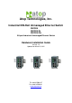

Atop Industrial Unmanaged Ethernet Switch
EH2006 / EH2005-Fs / EH2005-Fm
Hardware Installation Guide Version 1.4
Copyright c 20 10 ATOP Technologies, Inc.
All rights reserved
- 2 -
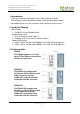
4. Hardware Installation
Step1: Connect to Power
Prepare suitable DC 9~30V power source and connected to EH switch by 3-pin
Terminal blocks.
You can connected two DC input for power auto-backup need.
Check P1/P2 LED for correct power source, everything is OK if the LED(s) was
lighted
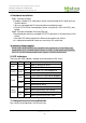
Step2: Connect to Network Device by Ethernet
Connected your device by standard UTP/STP cable with RJ-45 connectors to EH
switch.
The LINK LED will be lighted if the Ethernet connection was linked.
It is indicated and blinked if data was transfer by EH switch hub.
UL Notice for Power supplier
All the series of EH products are intended to be supplied by a Listed Power Unit
marked with ¡LPS¡, ¡Limited Power Source¡ or ¡Class 2¡ and output rate 9-30VDC,
0.6A. Or, use the recommended power supply in ¡Optional Accessories.
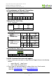
5. LED Indicators
There are four LED indicators located at the front panel of EH series.
Name
LED Status
Description
Off Both P1 and P2 on or off
ALM Green
On Either P1 or P2 on
Off Power input 1/2 is not plugged yet
P1/P2
Green
On Power status is Ready
Off Link is Boren or Cable not be plugged
Green
Blink Traffic be indicted for data transfer
Off 10M rate be active
RJ45
Yellow
On 100M rate be active
Off No data be transmitted
Data
Blink Working when data transmitted
Off No media be available
Fiber
SC/ST
Link
On Working when media was ready
7. Configuration and Setting Methods
Any settings or configurations are unnecessary.