ATTO Technology, Inc. ATTO FibreBridge Installation & Operations Manual FibreBridge 2100R, 2200R/D and 3200R © 2000 ATTO Technology, Incorporated. All rights reserved. All brand or product names are trademarks of their respective holders. No part of this manual may be reproduced in any form or by any means without the express written permission of ATTO Technology, Incorporated. Rev.
ATTO Technology, Inc. ATTO FibreBridge Installation & Operation Manual ATTO Technology, Inc.
ATTO Technology, Inc. ATTO FibreBridge Installation & Operation Manual CHAPTER 1: INTRODUCTION..............................................................................................................................................1 FIBRE BRIDGE PRODUCT MODULE DESCRIPTION .................................................................................................................... 1 FC RACK SYSTEM PRODUCT DESCRIPTION ..............................................................................
ATTO Technology, Inc. ATTO FibreBridge Installation & Operation Manual SCSI TERMINATION .................................................................................................................................................................. 21 FIBRE CHANNEL CABLING........................................................................................................................................................ 22 GBICS..........................................................................
ATTO Technology, Inc. ATTO FibreBridge Installation & Operation Manual APPENDIX B: RADIO AND TELEVISION INTERFERENCE...................................................................................46 APPENDIX C: CIRCUIT BOARD DIMENSIONS & IMPORTANT JUMPER LOCATIONS..........................48 APPENDIX D: FIBRE CHANNEL RESOURCES...........................................................................................................51 APPENDIX E: FIBRE CHANNEL ACCESSORIES ...............................
ATTO Technology, Inc. Chapter 1: ATTO FibreBridge Installation & Operation Manual INTRODUCTION This manual will provide an overview of the various ATTO FibreBridge products and product modules as well as describe how to install and configure the bridge for optimal operation.
ATTO Technology, Inc. ATTO FibreBridge Installation & Operation Manual Fibre Channel Technology Fibre Channel is a serial communications interface designed for the transfer of large amounts of data between a variety of hardware systems over long distances. It is becoming a key technology for applications that require shared, high bandwidth access to storage.
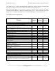
ATTO Technology, Inc. Chapter 2: ATTO FibreBridge Installation & Operation Manual ATTO FibreBridge™ Benefits and Features The different ATTO FibreBridge Product Modules come with a variety of features in an effort to offer users a choice of cost-effective as well as high end solutions for including native SCSI devices into a Fibre Channel Storage Area Network (SAN). Below is a list of some of the key features available, followed by a table identifying which features are offered in the different models.
ATTO Technology, Inc. ATTO FibreBridge Installation & Operation Manual can support F_Ports or FL_Ports and automatically configure itself. ATTO Technology recommends that this mode of operation not be used. It is better to force the port to the desired mode. When connecting the bridge to a F_Port device, set the port connection mode to “Point-to-Point.” When connecting to a FL_Port device, set the port connection mode to “Loop”.
ATTO Technology, Inc. Chapter 3: ATTO FibreBridge Installation & Operation Manual ATTO FC Rack Enclosure and Power Modules This chapter provides an overview of the ATTO FC Rack System and the Power Modules, as well the installation process for the Power Modules. The main enclosure of the ATTO FC Rack System houses all ™ the FibreBridge Product Modules and Power Modules. There are two bays for FibreBridge Product Modules and two bays for Power Modules. Physical Dimensions Figure 3.
ATTO Technology, Inc. ATTO FibreBridge Installation & Operation Manual Figure 3.3 Side view with hole dimensions in inches (mm in parentheses) Environmental The ATTO FC Rack System is designed to operate in an environment that is 0°-40° C, 0-90% humidity and non-condensing. Cooling Airflow Each Power Module provides a total of 16 CFM of airflow. A system that has two Power Modules installed will have a total of 32 CFM of airflow.
ATTO Technology, Inc. ATTO FibreBridge Installation & Operation Manual Internal Power Distribution The ATTO FC Rack System provides a redundant power scheme with two "hot swappable" Power Supply Modules. Each Power Supply Module feeds 12V to the backplane. From there, the power is distributed to the bridge modules and the fans. A failure of one power supply will not affect the functionality of the bridge modules or the cooling system since the second supply is still supplying power to the backplane.
ATTO Technology, Inc. • ATTO FibreBridge Installation & Operation Manual Power Draw: The maximum power draw is 2 Amps @ 110 Volts for the entire ATTO FC Rack System. When the ATTO FC Rack System has two Power Modules, the entire unit will still draw only 2 Amps @ 110 Volts. LED Indicator The green LED indicator on the Power Module will light when the module is correctly installed and the switch is turned on. This LED indicates that power is being drawn from this module and is available on the backplane.
ATTO Technology, Inc. ATTO FibreBridge Installation & Operation Manual Step 5. Turn the power switch on the power module to the on position. Verify that the green LED is illuminated. The correct method for removal of a power module is as follows: Step 1. The power switch on the rear of the power module must be in the off position. Make sure the power LED is NOT illuminated. Step 2. Disconnect the power cord from the power module as well as the AC power source. Step 3.
ATTO Technology, Inc. Chapter 4: ATTO FibreBridge Installation & Operation Manual ATTO FibreBridge™ Product Module Integration This chapter provides an overview of the ATTO FibreBridge Product Modules and their installation process. ATTO FibreBridge module is designed to slide into and mount to either of the two module bays on the main FC Rack Enclosure chassis. The bridge module must be inserted into the face of the rack chassis where the cooling grids are located.
ATTO Technology, Inc. ATTO FibreBridge Installation & Operation Manual Figure 4.2 ATTO FibreBridge Power Connector Figure 4.3 ATTO FibreBridge 2100R Product Module Figure 4.4 ATTO FibreBridge 3200R Product Module ATTO Technology, Inc.
ATTO Technology, Inc. ATTO FibreBridge Installation & Operation Manual Fibre Channel Ports The Fibre Channel ports on the bridge modules are used to connect the bridge into either a Fabric or Arbitrated Loop. Some of the features for the Fibre Channel ports include: • • • • • 1.
ATTO Technology, Inc. • • ATTO FibreBridge Installation & Operation Manual Single Ended Ultra SCSI – 40 MB/sec max per bus High Voltage Differential (HVD) Ultra SCSI – 40 MB/sec max per bus Each of the two ports is totally independent from the other. This means that each bus is capable of 15 devices and each bus is capable of 40/80 MB/sec (Ultra/Ultra2). There are a few advantages to this. First, you are able to use software striping to create a RAID 0 group that includes devices from both SCSI busses.
ATTO Technology, Inc. ATTO FibreBridge Installation & Operation Manual FC Activity – This LED blinks to show activity occurring on the Fibre Channel port of the unit. The LED may appear to be steadily lit during times of very high activity. SCSI 1 Activity, SCSI 2 Activity – One LED for each SCSI bus displays activity on that SCSI bus. Ready – A few seconds after power has been applied, the Ready LED should be illuminated.
ATTO Technology, Inc. Chapter 5: ATTO FibreBridge Installation & Operation Manual FibreBridge™ 2200R/D This chapter provides an overview of the ATTO FibreBridge 2200R/D. The FibreBridge 2200R/D is a Fibre Channel to SCSI bridge for high throughput enterprise environments that is designed for cost sensitive implementations.
ATTO Technology, Inc. ATTO FibreBridge Installation & Operation Manual The physical dimensions of the FibreBridge 2200R/D are 16.725" W x 10"D x 1.72"H (424.5mm W x 253.8mm D x 43.7mm H) Mounting The FibreBridge 2200R/D was designed with all of the cable connections and the power switch on one side, while the LED indicators are on the opposite side. When mounting this unit into a rack, the "L"brackets can be installed so that either the LED side of the bridge or the connector side can be facing front.
ATTO Technology, Inc. ATTO FibreBridge Installation & Operation Manual Environmental The FibreBridge 2200 is designed to operate in an environment that is 0°-40° C, 0-90% humidity and noncondensing. Cooling and Airflow There are two fans in the FibreBridge 2200R/D. Each can provide approximately 3 CFM of airflow. Cooling is from side to side where air enters in from the left side and is exhausted out the right. Ambient air near the inlets should not exceed 40°C.
ATTO Technology, Inc. ATTO FibreBridge Installation & Operation Manual Figure 5.6 FibreBridge 2200R/D Connector Face Fibre Channel Port The Fibre Channel port on the bridge is used to connect the bridge into either a Fabric or Arbitrated Loop. Some of the features for the Fibre Channel port include: • • • • • 1.
ATTO Technology, Inc. ATTO FibreBridge Installation & Operation Manual possible to connect slower “Legacy” devices of one SCSI bus of the bridge while connecting faster devices on the second. Each bus can communicate at independent rates. The ATTO FibreBridge supports a wide variety of SCSI storage devices including stand-alone drives, removable drives, JBODs, RAIDs, Tape, CD and DVD drives, changers, libraries, magneto optical drives, Jaz and Zip devices. LED Indicators Figure 5.
ATTO Technology, Inc. Chapter 6: ATTO FibreBridge Installation & Operation Manual Cabling a FibreBridge ™ “Quick” Installation Instructions 1. Connect SCSI devices to the ATTO FibreBridge using a SCSI cable with a 68-pin fine pitch or “P” connector for each port on the bridge. The bridge is terminated internally. Be aware of cable limitations for the SCSI bus, which are: • Three (3) meters and four devices, or one and a half (1.
ATTO Technology, Inc. ATTO FibreBridge Installation & Operation Manual For best performance, keep SCSI cabling distances as short as possible. A FibreBridge with an LVD SCSI personality module is downward compatible with Single Ended Ultra SCSI as well as Fast, Wide, or Narrow SCSI devices. The entire SCSI bus will operate at the speed of the slowest device. If you wish to mix devices of different SCSI speeds on the bridge, it is best to separate them.
ATTO Technology, Inc. ATTO FibreBridge Installation & Operation Manual Both ends of each SCSI bus require termination. The ATTO FibreBridge has built-in automatic termination. A terminator does need to be placed on the bus after the last SCSI device. It is important that the correct type of terminator be used for the type of bridge being used: LVD, HVD, or SE. ATTO FibreBridge Built in Termination Termination Figure 6.
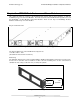
ATTO Technology, Inc. ATTO FibreBridge Installation & Operation Manual The FibreBridge modules do not come standard with GBIC modules. They must be ordered separately. GBIC Module and GBIC Guide System Figures 6.3 and 6.4 depict a typical GBIC and GBIC guide system. GBICs may be removed and replaced with the power on. Figure 6.3 GBIC Module Figure 6.4 GBIC Guide System GBIC Installation Instructions 1. Orient the GBIC as shown in Figure 6.5. The keyway is ON THE BOTTOM for the port insertion. 2.
ATTO Technology, Inc. ATTO FibreBridge Installation & Operation Manual Figure 6.5 GBIC Installation GBIC Removal Instructions 1. Disconnect the cable (if one is connected) from the GBIC being removed. 2. Using the thumb and forefinger of one hand, grasp the GBIC latches and squeeze them toward the center of the GBIC. While squeezing, withdraw the GBIC from the chassis.
ATTO Technology, Inc. ATTO FibreBridge Installation & Operation Manual DB-9 Connector Bottom Figure 6.7 MIA – DB9 Connector MIA Installation Connect the MIA to the FibreBridge by plugging the male DB9 connector on the MIA to the female DB9 connector on the bridge. Be sure to secure the MIA to the DB9 connector. Connect a fiber optic cable, with SC type connectors to the MIA. Each connector on an MIA is different; one acts as a transmitter and the other as a receiver.
ATTO Technology, Inc. Chapter 7: ATTO FibreBridge Installation & Operation Manual FibreBridge Services Monitoring and Managing the ATTO FibreBridge The ATTO FibreBridge Services can be used to configure and tune the bridge for many different environments and applications, update the firmware, configure the addresses of the connected SCSI devices, monitor internal power and temperature status, report on hardware diagnostics and log failures.
ATTO Technology, Inc. ATTO FibreBridge Installation & Operation Manual 1) Connect a DB9 crossover serial cable (null modem) between the ATTO FibreBridge serial port and one of the computer's serial COM ports. A gender changer or DB-9 to DB-25 converter may be needed depending on the cables being used. 2) Enable the computer’s serial port and initiate a terminal emulation link.
ATTO Technology, Inc. ATTO FibreBridge Installation & Operation Manual b) At the FibreBridge Configuration Menu, select option Network Configuration c) At the Network Configuration Menu, select option IP Gateway d) Enter the desired IP Gateway 5) To set the FibreBridge Name, follow the instructions below: a) At the FibreBridge main Menu, select option FibreBridge Configuration b) At the FibreBridge Configuration Menu, select option FibreBridge Name [“ “] c) Enter the desired FibreBridge Name.
ATTO Technology, Inc. ATTO FibreBridge Installation & Operation Manual 3) Login to the ATTO FibreBridge. The username that the bridge will accept is sysadmin. Enter userid as the password. 4) Make sure that the FTP program is in Binary mode. Tip: When using FTP with the FibreBridge 3200R, remember to close the connection using a standard FTP CLOSE command or similar process before exiting the FTP program. ATTO Technology, Inc.
ATTO Technology, Inc. Chapter 8: ATTO FibreBridge Installation & Operation Manual Serverless Backup Support What is Serverless Backup? Serverless Backup is an application that allows data to be copied between two storage devices (Fibre Channel disks, SCSI disks and SCSI tapes) with minimal to no intervention from a server. As the volume of data on a network grows, the resources required to back up this data also grow.
ATTO Technology, Inc. ATTO FibreBridge Installation & Operation Manual The Extended Copy command contains target and segment descriptors that are used to define which data is to be moved between which devices. With Serverless backup, the server sends a single Extended Copy command to the FibreBridge. The bridge then interprets the segment descriptors and issues read commands to the appropriate devices. Once enough data is read, the bridge will issue write commands to the appropriate device.
ATTO Technology, Inc. Chapter 9: ATTO FibreBridge Installation & Operation Manual Updating the Firmware Within the FibreBridge Flashing the FibreBridge The FibreBridge has four separate processors controlling the flow of data.
ATTO Technology, Inc. ATTO FibreBridge Installation & Operation Manual Chapter 10: Addressing SCSI Devices The FibreBridge is very dynamic in how SCSI devices are mapped into Fibre Channel addresses. This allows the user to virtually have any possible SCSI configuration. An overview of device addressing is given below. Refer to Appendix A for a detailed explanation of the FibreBridge addressing methodology.
ATTO Technology, Inc. 5. ATTO FibreBridge Installation & Operation Manual Select the Fibre Channel tab from the main window. 5.1. From within the Fibre Channel panel, the FibreBridge can be set to use Hard Addressing if desired. Default = Soft Addressing. 5.2. Select the value of the Hard Address. Default value = 3. 5.3. Set the FibreBridge Soft Fibre LUN to the desired value. Default value = 14 6. Select the Save/Restore Tab within BridgeTools.
ATTO Technology, Inc. ATTO FibreBridge Installation & Operation Manual Default Address Translation The default Address Translation method should be sufficient for most configurations.
ATTO Technology, Inc. ATTO FibreBridge Installation & Operation Manual Appendix A: Fibre Channel to SCSI Address Mapping The ATTO Technology FibreBridge allows parallel SCSI devices to participate in a Fibre Channel arbitrated loop or on a fabric. Fibre Channel and parallel SCSI use different models to address devices. The FibreBridge translates between these addressing models.
ATTO Technology, Inc. ATTO FibreBridge Installation & Operation Manual Fibre Channel Addressing Fibre Channel World Wide Name (WWN) Each Fibre Channel device is assigned a unique World Wide Name (WWN). The WWN is used to identify all Fibre Channel devices. The 64-bit WWN has the following format: Field Name Byte Value WWN Format 0 1 20 00 2 00 Company ID 3 10 4 86 5 xx Device ID 6 xx 7 xx The WWN Format field indicates the format of the remaining fields in the WorldWide Name.
ATTO Technology, Inc. ATTO FibreBridge Installation & Operation Manual SCSI Target Identifier The SCSI Target Identifier indicates the SCSI ID assigned to the target. Each device on the same physical SCSI bus must be assigned a unique SCSI ID. A Wide (16-bit) SCSI bus will support a maximum of 16 SCSI IDs (including the SCSI ID assigned to the FibreBridge). SCSI Logical Unit Number The SCSI Logical Unit Number indicates the logical unit being addressed within the specified target.
ATTO Technology, Inc. 15 14 Address Method 13 12 ATTO FibreBridge Installation & Operation Manual 11 10 Bit Number 9 8 7 6 5 4 3 2 1 0 Address Method Specific Definition Bits 15-14 contain the Address Method code. This code is used to determine how the remaining 14 bits are to be interpreted by SCSI devices. The following table defines the available Addressing Methods.
ATTO Technology, Inc. ATTO FibreBridge Installation & Operation Manual parameter allows the host to specify that the peripheral device addressing method will be used regardless of the Addressing Method field in the first level address. This allows custom address translations to be built for systems that may not properly support hierarchical addressing.
ATTO Technology, Inc. ATTO FibreBridge Installation & Operation Manual This default method of addressing was developed with the assumption that not all host adapter manufacturers have designed the hierarchical addressing methodology into their products yet. Since the bit positions here are also easily modified in non-volatile RAM, this addressing will work with all host adapters that only use one byte of LUN addressing.
ATTO Technology, Inc. ATTO FibreBridge Installation & Operation Manual and the Report LUNs command as described in the next section. FibreBridge hierarchical addressing is limited to the first-level LUN support. More information is available in the reference documentation. SCSI-3 REPORT LUNs Command The SCSI-3 Report LUNs command returns a sorted list of LUNs available (at the time of execution of the Report LUNs command) on the FibreBridge.
ATTO Technology, Inc. ATTO FibreBridge Installation & Operation Manual 1 containing even numbered LUNs (the bus bit is the LUN byte is always 0) while Bus 2 will only have odd numbered LUNs (the bus bit is the LUN byte is always 1). Some Fibre Channel host adapters are set to only address LUNs 0 through 7 by default. This corresponds to only the first three bits in byte 1 of the FCP_LUN field. The bus designator is taking up one of these bits, leaving only two of the Target bits to address devices.
ATTO Technology, Inc.
ATTO Technology, Inc. 15 0 14 0 13 12 ATTO FibreBridge Installation & Operation Manual 11 10 N/A 9 Bit Number 8 7 6 5 4 LUN 3 2 1 Target 0 Bus This mapping will allow for two RAID controllers on each FibreBridge SCSI bus (with SCSI IDs 0 and 1).
ATTO Technology, Inc. ATTO FibreBridge Installation & Operation Manual Appendix B: Radio and Television Interference The equipment described in this manual generates and uses radio frequency energy. If this equipment is not used in strict accordance with the manufacturer's instruction, it can and may cause interference with radio and television reception. See the Technical Specification sheet for the ATTO FibreBridge Product Module for a full list of certifications for that particular model.
ATTO Technology, Inc. ATTO FibreBridge Installation & Operation Manual Further results of FCC Testing "In certain instances, extraordinary variances in the AC power supplied to this unit will require the operating system's normal error recovery procedure to retry the current SCSI command. In this case, the unit can fully recover with no loss of data, and without user intervention.
ATTO Technology, Inc. ATTO FibreBridge Installation & Operation Manual Appendix C: Circuit Board Dimensions & Important Jumper Locations Maximum Height = 1.582” (4.015 cm) Figure C-1 ATTO FibreBridge 2100R Product Module Board Layout ATTO Technology, Inc.
ATTO Technology, Inc. ATTO FibreBridge Installation & Operation Manual Maximum Height = 1.272” (3.228 cm) Figure C-2 ATTO FibreBridge 2200R/D and 3200R Product Modules’ Board Layout ATTO Technology, Inc.
ATTO Technology, Inc. ATTO FibreBridge Installation & Operation Manual Figure C-3 ATTO FibreBridge 3200R Connector Layout ATTO Technology, Inc.
ATTO Technology, Inc. ATTO FibreBridge Installation & Operation Manual Appendix D: Fibre Channel Resources To learn more about Fibre Channel, investigate the following resources: • • • • • • Fibre Channel Industry Association – www.fibrechannel.com FibreAlliance Celestra Consortium Storage Area Networking Industry Association (SNIA) – www.snia.org Cern – www.cern.ch Fibre Channel Consortium – www.iol.unh.edu ATTO Technology, Inc.
ATTO Technology, Inc. ATTO FibreBridge Installation & Operation Manual Appendix E: Fibre Channel Accessories The following is a list of Fibre Channel accessories that are available through ATTO Technology. Contact an ATTO Technology authorized sales representative to order any of these.
ATTO Technology, Inc. ATTO FibreBridge Installation & Operation Manual CBL-HSDB-010 .... HSSDC to DB9 Copper Fibre Channel Cable (Unequalized) – 10m. CBL-HSHS-003 .... HSSDC to HSSDC Copper Fibre Channel Cable (Unequalized) – 3m. CBL-HSHS-010 .... HSSDC to HSSDC Copper Fibre Channel Cable (Unequalized) – 10m. Cables/Optical CBL-FCFI-005...... 5 Meter Cable-Duplex 50 Micron Multi-mode FC/Optical CBL-FCFI-010...... 10 Meter Cable-Duplex 50 Micron Multi-mode FC/Optical CBL-FCFI-030......
ATTO Technology, Inc. ATTO FibreBridge Installation & Operation Manual Appendix F: How to Contact ATTO Technology, Inc. Customer service, sales information and technical support are available by phone Monday through Friday, Eastern Standard Time 8:00 a.m. to 8:00 p.m., or by fax and web site 24-hours a day. ATTO Technology, Inc. 155 CrossPoint Parkway Amherst, New York 14068 (716) 691-1999 • voice (716) 691-9353 • fax http://www.attotech.