
- ATTO FibreBridge Installation & Operations Manual


ATTO Technology, Inc. ATTO FibreBridge Installation & Operation Manual
- 5 -
ATTO Technology, Inc.
Chapter 3: ATTO FC Rack Enclosure and Power Modules
This chapter provides an overview of the ATTO FC Rack System and the Power Modules, as well the
installation process for the Power Modules. The main enclosure of the ATTO FC Rack System houses all
the FibreBridge
™
Product Modules and Power Modules. There are two bays for FibreBridge Product
Modules and two bays for Power Modules.
Physical Dimensions
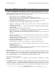
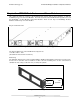
Figure 3.1 Rear view with dual redundant power supplies
The physical dimensions of the ATTO FC Rack System are
17.4" W x 17"D x 1.72"H
(441.6mm W x 431.5mm D x 43.7mm H)
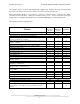
Mounting
The ATTO FC Rack System can be installed with the ATTO Product Modules facing the front or the back
because the "L"-brackets can be installed on either end. The mounting holes on the "L"-bracket fit a
standard 19” rack, using a centered 1.25” (31.7mm) hole pattern.
Figure 3.2 "L" Mounting Bracket
1.25”
(31.7mm)
1.72”
(43.6mm)