System 10 Stompbox Digital Wireless System Installation and Operation ATW-1501 Stompbox Wireless System
System 10 Stompbox Installation and Operation CAUTION RISK OF ELECTRIC SHOCK DO NOT OPEN WARNING: TO REDUCE THE RISK OF FIRE OR ELECTRIC SHOCK, DO NOT REMOVE SCREWS. NO USER-SERVICEABLE PARTS INSIDE. REFER SERVICING TO QUALIFIED SERVICE PERSONNEL. WARNING: TO REDUCE THE RISK OF FIRE OR ELECTRIC SHOCK, DO NOT EXPOSE THE APPLIANCE TO RAIN OR MOISTURE. CERTIFICATION: THIS DEVICE COMPLIES WITH PART 15 OF THE FCC RULES. THIS DEVICE COMPLIES WITH INDUSTRY CANADA LICENSE-EXEMPT RSS STANDARD(S).
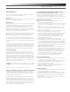
System 10 Stompbox Installation and Operation System 10 wireless ensures clear communications by providing three levels of diversity assurance: frequency, time, and space. Frequency Diversity sends the signal on two dynamically allocated frequencies for interference-free communication. Time Diversity sends the signal in multiple time slots to maximize immunity to multipath interference. Finally, Space Diversity uses two antennas on each transmitter and receiver to maximize signal integrity.
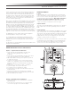
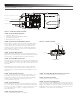
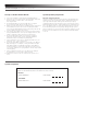
System 10 Stompbox Installation and Operation Microphone / Instrument Level Control Pairing Switch Screwdriver System ID Display Battery Compartment Figure C — ATW-T1001 UniPak® Transmitter UniPak® Transmitter Battery Installation 1. Slide off the battery cover. 2. Carefully insert two fresh AA alkaline batteries, observing polarity markings. 3. Replace the battery cover (Fig. C).
System 10 Stompbox Installation and Operation System Operation Turn down the mixer/amplifier level before starting up the wireless system. Do not switch on the transmitter yet. Receiver on... Plug the power supply into an AC power source. The blue System ID number on the front panel will illuminate. Transmitter on...
System 10 Stompbox Installation and Operation Ten Tips to Obtain the Best Results System Operating Frequencies 1. Use only fresh alkaline or fully charged rechargeable batteries. 2. Position the receiver so that it has the fewest possible obstructions between it and the normal location of the transmitter. Line-of-sight is best. 3. The transmitter and the receiver should be as close together as conveniently possible, but not less than 3' (1 m). 4.
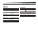
System 10 Stompbox Installation and Operation Specifications OVERALL SYSTEM Operating Frequencies Dynamic Range Total Harmonic Distortion Operating Range 2.4 GHz ISM band (2400 to 2483.5 MHz) >109 dB (A-weighted), typical <0.05% typical 18.3 m (60') radius, 36.
System 10 Stompbox Installation and Operation To reduce the environmental impact of a multi-language printed document, product information is available online at www.audio-technica.com in a selection of languages. Afin de réduire l’impact sur l’environnement de l’impression de plusieurs langues, les informations concernant les produits sont disponibles sur le site www.audio-technica.com dans une large sélection de langue.