
User Manual

System 10 Stompbox Installation and Operation
3
System 10 wireless ensures clear communications by providing three
levels of diversity assurance: frequency, time, and space. Frequency
Diversity sends the signal on two dynamically allocated frequencies
for interference-free communication. Time Diversity sends the signal
in multiple time slots to maximize immunity to multipath interference.
Finally, Space Diversity uses two antennas on each transmitter and
receiver to maximize signal integrity.
Each System 10 Stompbox professional digital wireless system includes
an ATW-R1500 Stompbox receiver, an ATW-T1001 UniPak body-pack
transmitter with an AT-GcW guitar cable, and hook & loop strips for
adding receiver to an effects pedal board. All A-T Wireless Essentials
®
microphones and cables, available separately, are pre-terminated for
use with any ATW-T1001 transmitters. Note: ATW-T1001 transmitt
ers
from earlier System 10 models may not be compatible with the multi-
transmitter pairing and battery level indicator functions of the System 10
Stompbox receiver. However, these older transmitter models may be
shipped to the Audio-Technica Service Department for firmware updates.
The ATW-R1500 receiver includes a switching power supply that
automatically adapts to changes in mains voltage.
The versatile ATW-T1001 UniPak body-pack transmitter has both
a high-impedance input for instruments, and a low-impedance input
with bias connection for use with dynamic and electret condenser
microphones.
The transmitter uses internal AA batteries and has a Power/Mute switch
and input Trim (level) adjustment.
Receiver Installation
Location
For best operation, the receiver should be at least 3' (1 m) away from
a wall or metal surface to minimize reflections. Keep the receiver away
from noise sources such as other digital equipment, microwave ovens,
as well as away from large metal objects. Keep System 10 Stompbox
receiver 30' (9 m) away from wireless access points. Operating
transmitters should be kept at least 3' (1 m) from receiver, but will
continue to work up to 60' (18 m) from receiver line of sight.
Output Connection
There are two switched TRS balanced ¼" output jacks on the side panel.
Either output can be connected to a guitar amp, a tuner or an effects
pedal.
Power Connection
Connect the DC plug on the included AC power adapter to the DC power
input on the back of the receiver. Then plug the adapter into a standard
120 Volt 60 Hz or 230 Volt 50 Hz (depending on global location) AC power
outlet. The receiver may also be used in conjunction with an effects
pedal board with a common power supply, but each output must be
“isolated” in order to prevent noise interference.
(Note that the receiver has no power Off/On switch. The receiver will be
energized whenever the power adapter is connected and plugged into
the AC outlet. Unplug the power supply from the AC outlet when the
system is not in use — both for safety, and to conserve energy.)
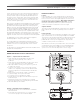
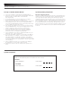
ATW-R1500 Receiver Controls and Functions
Figure A — Top Panel Controls and Functions
1. Audio Output B: Switched TRS balanced ¼" phone jack.
Can be connected to guitar amp, tuner or effects
pedal input.
2. Audio Output A: Switched TRS balanced ¼" phone jack. Can be
connected to guitar amp, tuner or effects pedal input.
3. A/B Output Indicators: Glows green if output is on, glows red
if output is off or muted.
4. System ID Select Switch: Press to cycle through System ID
numbers or to clear pairing. (System ID is an identical number
assigned to a paired receiver and transmitter for identification
purposes.)
5. Pairing Switch: Press and hold to initiate or clear pairing.
6. System ID Display: Shows System ID number.
7. Foot Switch: Press to toggle between outputs.
8. AF Peak Indicator: Only lights when audio distortion is present
at maximum input.
9. Pair Indicator: Glows green to indicate presence of paired
transmitter. Also blinks green to indicate pairing mode activated.
10. Transmitter Battery Power Indicator
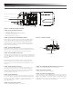
Figure B — Rear Panel Controls and Functions
1. Output Mode Selector: Use to switch between A or B Mode
and A Mute Mode.
2. Power Input Jack: Universal (center + or -) 9V-12V DC input.
Connect the DC plug from the included AC adapter.
1
2
3
7
9
54 6
1
2
10
8