
Owner's Manual


holes
be
at least 3/4" (19mm) away from joists or studs whenever
possible
to
allow clearance for
the
toggle clamps.
Once the speaker locations are established use the cardboard
template or the plastic compass provided with your speaker to draw
the speaker cut-out. The hole diameters for
the
various speakers are
marked on the compass.
The
cardboard templates may also
be
used
as a visual aid for placement of the speakers.
To
do this, temporarily
hold the templates in place with a push tack or tape.
Using the proper tool
cut
the
appropriate sized
hole in the ceiling.
On
drywall, clean cuts can
be
made with a drywall saw. Make sure to clean the
excess debris from the front face
of
the hole to
ensure a flush fit.
If
the
cable has not yet been run, do
so
now
that
you have better access
to
the
ceiling. Once
the
speaker cable has
been run, pull the end
of
the cable
out
of
the
speaker cut-out, strip
back a section
of
the
jacket
as needed, and then expose
½"
(13mm)
of each conductor.
To
aid in speaker performance, a
fibrous
material,
such as
fiberglass, may be placed behind
the
speaker. This may also help
to
reduce unwanted sound from being
transmitted
into adjoining
rooms.
If
the
ceiling space has blown
or
loose insulation, care
must
be taken
to
prevent
the
loose
insulation
from
entering
the
back
of
the
speaker. This can be accomplished by placing a
batt
of
fiberglass insulation,
fabric
barrier,
or
bag over
the
back
of
the
speaker. Placing a rigid enclosure behind the speakers can
be
done but the enclosure should
be
large enough not
to
degrade
the performance
of
the
speaker. Rigid enclosures
of
less than 0.75
cu
ft
(21
liters) should be stuffed with acoustic insulation such as
fiberglass.
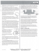
As
the drawing shows,
the
speakers utilize
Toggle Clamps which,
after
tightening,
hold
the
speakers in place. Ensure
that
the toggle clamps are rotated into
their
"Home" position prior
to
installation.
Verify
that
the
speaker
fits
properly into
the
cut
-out and then remove
the
speaker
from the hole.
@
Connect
the
wire conductors
to
the terminals on
the
back
of
the
speaker by depressing each spring terminal, inserting
the
wire into
the hole, and releasing
the
terminal.
Use
care to observe
the
proper
polarity(+ &
-).
Speakers wired out
of
phase
will
exhibit an apparent
loss of bass response.
Note: Dual-channel (Single-Point
Stereo)
speakers have both
the
left and right channel connections on
the
same speaker. Ensure
that
both channels are connected and in phase. An out
of
phase
connection to a dual-channel speaker
will
be immediately obvious
when signal is applied since there will be
little
if
any bass output. If
disconnecting one
of
the
inputs increases
the
bass
output
then
the
inputs are out
of
phase.
frameless
For:
6· 1 /2"
In-Ceiling
Insert the speaker into the hole and tighten
the
four
toggle screws.
As
you
start
to
turn
each screw the toggle clamps
will
rotate outward
to engage
the
ceiling or wall material as shown.
CAUTION:
DO
NOT
OVER-TIGHTEN
THE
CLAMPS.
Too
much torque may damage
the
toggle, causing
the
speaker not
to
seat securely. A snug
fit
is all
that
is necessary
to
assure proper performance.
--
Tighten4
--
Phillips
screws
Clean
front
edge
of
cutout
to
ensure
a
flush
fit.
If
your speaker includes a pivoting tweeter aiming
it
toward the
listening area
will
raise the amplitude of
the
highest frequencies
(>12kHz), adding brilliance.
USE
CARE
TO
AVOID
DAMAGING
THE
DOME
OFTHE
TWEETER
WHEN
AIMING!
The grilles can
be
painted using multiple light coats
of
spray paint.
Custom color spray paints are available from specialty companies.
Contact your dealer for more information.
The
grilles should
be
removed from
the
speaker and painted in a clean environment
to
prevent contamination. It is best
to
go
around
the
grilles and apply
the
paint from multiple angles.
DO
NOT
remove the scrim cloth from
the
backside
of
the
grille. It is not replaceable.
Attach
the
grilles
to
the
speakers and enjoy. Should you wish
to
remove
the
grilles from
the
speakers
pull
at
the
grilles' edge.
Initially there
will
be significant resistance because
the
grilles are
magnetically attached.
WARRANTY
- LIFETIME
LIMITED
AudioSource will repair or replace any product found
to
be
faulty
due
to
defects in
material or workmanship,
with
new or rebuilt parts, free
of
charge in
the
USA
, from
the
date
of
original purchase,
for
the
life
of
the
product. This is a no-hassle warranty
with
no
mail-in
warranty card needed. This warranty does not cover damages in
shipment
, failures caused
by
other products, or failures due
to
accident, misuse,
abuse, acts
of
God
, or alteration
of
the
equipment. This warranty is extended only
to
the
original purchaser. when purchased through an authorized resell
er
and a
purchase receipt, invoice, or other proof
of
original purchase date is provided. This
warranty gives you specific legal rights and you may have other rights (which vary by
area).
If
a problem
with
this
product develops
during
or
after
the
warranty period,
please
contact
AudioSource,your deal
er
, or any factory-authorized service center
for
service. Mail-in service can
be
obtained during
the
warranty period
by
visiting
AudioSource.net. A Return Authorization
(RA
) number
must
be
obtained in advance
and a copy
of
the
RA
form should be included inside
the
shipping carton.
In
sta
ll
Guide Rev. A
AudioSource
■
13970 SW 72nd AVE
■
Portland, OR
97223
www.audiosource.net
■
support@audiosource.net
page
2
of2