
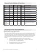
Owner's Manual


[
4
#
4360710
._
______
___.
87
8
1
6
87a
I
I
85
30
ORANGE
YELLOW
WHITE
RED
OPEN
#
1031118
#
1031295
#
1032707
(-
)
(
+)
# 1031119
#
1032708
LED
PORT
BLUE
GREEN
WHITE/RED
WHITE
BLACK
BROWN
RED
UNLOCK
OUTPUT
( - )
LOCK
OUTPUT
( - )
PARKING
LIGHT
INPUT
PARKING
LIGHT
OUTPUT
GROUND
SIREN
OUTPUT
BATTERY
12V
(
+)
SIREN
I
HORN
OUTPUT
POLARITY
JUMPER
OBI
PORT
PROGRAMMING
I
VALET
PORT
PURPLE
BLUE
GREEN
YELLOW
ORANGE
RED/WHITE
DOOR
TRIGGER
INPUT
( + )
TRUNK
PIN
INPUT
( - )
DOOR
TRIGGER
INPUT
( - )
IGNITION
INPUT
( + )
ARMED
OUTPUT
( - )
TRUNK
RELEASE
OUTPUT
( - )
STARTER
INTERUPT
RELAY
#1031123
86
-ARMED
OUTPUT
( - )
85-
IGNITION
( + )
87
A-
STARTER
OUTPUT
-
MOTOR
SIDE
30-
STARTER
INPUT-
KEY
SIDE
87-
OPEN
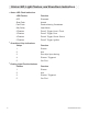
Security Trigger Zones
If the security system has been triggered the LED will flash
one
of
the patterns below
indicating the zone.
LED
FLASHES
TRIGGER
ZONE
2 Flashes
3
Flashes
4 Flashes
5 Flashes
Hood I Trunk Input
Door Input
Shock Sensor
Ignition Input
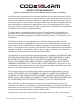
CCJCiE~IA~m
r:»r:lOFESSIONAL
SEr:liES
Security and Keyless Entry
Installation Quick Reference
Guide
for
model:
ca1055
Complete guides also available at
www
.voxxuniversity.com
201
7
Vo
u E
lectronics
Cor
p
orat
i
on.
All
r i g ht s
reserved
4
2S0770