TV55 Owner’s Manual Indoor/Outdoor Amplified TV Antenna
Safety Precautions TV55 Warning! Use extreme caution when installing or removing an outdoor antenna that is located close to overhead wires such as power lines, telephone lines or cable TV lines. If any part of the antenna makes contact with overhead power lines, touching the antenna or the antenna cable can cause electrocution and death. If the antenna is in contact with any type of overhead wires, call your power company and ask them to send a qualified technician to remove the antenna.
TV55 Please read and follow these important safety precautions: • Be sure to select an antenna site well away from all overhead wires. • Do not try to guess which overhead wires carry high voltage. Check with the Power Company. • If you notice anything making contact with the overhead wires, call the Power Company to have it removed safely. Do not run the downlead cable over power wires. • Get help from a qualified professional when removing the old antenna if there is any doubt of clearing overhead wires.
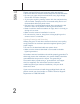
About Your New TERK TV55 Antenna TV55 Your TERK TV55 antenna is designed for both single and multifamily homes. It’s specifically engineered to provide superior reception of high-definition (HDTV), digital television (DTV) and VHF/UHF TV channels in most viewing locations. The TV55’s unique antenna technology and patented Dual-Mode integrated powered amplifier produce the clearest, cleanest signals available from a compact, unobtrusive design that blends well with any home decor.
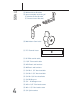
TV55 (2) Window Mount Brackets (2)-piece assembly consisting of: (1) Window Frame Bracket (1) Channel Insert Bracket) (2) Wall-Mount Cam-locks (1) 7.
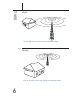
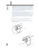
Positioning the TV55 TV55 The TV55 MUST be mounted horizontally (See Fig 1.); with the front of the TV55 facing the general direction of the TV station’s broadcasting transmitters. See Fig 2. The higher the elevation of the antenna, the better the reception performance will be. Pointing the Antenna Towards the Broadcast Tower 1. Go to www.terk.com and click on the “Antenna Locator” link. 2. Enter your home address and then “Submit.” 3.
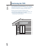
TV55 Right On the side of the house facing the broadcast tower Fig 2.
Mounting the TV55 Antenna TV55 Mounting Options: The TV55 can be mounted in many ways both indoors (such as on a wall or in an attic) and outdoors (such as on a mast, on a wall, or either under a window or a roof’s eave). Decide where you will mount the TV55 and follow the appropriate directions. Indoors/Outdoors using Wall Mount Brackets Indoors Select a spot in your home where the antenna may be positioned horizontally and out of the way of large metal objects which may cause interference.
TV55 3. Use the #10 screws and plastic anchors to secure each of the Wall-Mount Cam-lock units into the wall at the marks made in Step #2. (As an alternative mounting method, you may choose to use longer screws directly attached into wood supports, wall studs, or use a different wall-anchoring device.) Make sure the Cam-lock wings are vertical. See Fig 3. 4. Carefully position the TV55 antenna so that the Cam-locks slide into the channel on the rear of the antenna. See Fig 4. 5.
Mounting the TV55 Antenna (continued) TV55 Outdoors using Window Mounting: 1. Locate: (1) Channel Insert (2) 3/4" bolts (2) Hex-head nuts (2) Split washers (2) Window Mount Brackets Plastic anchors and screws (depending on the material being mounted to) 2. Break the Channel Insert into 2 pieces at the score line. See Fig 6. Note: Do not break Channel Insert if mounting on a mast. See the “Mast Mounting” section. Fig 6.
TV55 3. Insert a hex-head bolt into each of the Channel Inserts. Insure that the bolt head fits into the hexagon recess on the insert. 4. Slide the Channel Inserts into the channel on the back of the TV55 - the bolts should be pointing away from the antenna. See Fig 7. Fig 7. 5. Unscrew the Window Mount Bracket so you can separate the two pieces (Channel Insert Bracket and Window Frame Bracket) – keep the screw since you will need to use it again. 6.
Mounting the TV55 Antenna (continued) TV55 7. Determine the location on the window where the TV55 will be mounted. 8. Attach the Window Frame Brackets to the window. Be sure the brackets are level and line up with the channel inserts already on the antenna. 9. Insert the Channel Insert Brackets attached to the antenna into the slots on the Window Frame Brackets already mounted on the window. Reattach the brackets with the screw removed earlier. See Fig 9. Fig 9. 10.
TV55 Outdoors using Mast Mounting: 1. Locate: (1) Channel Insert (1) Mast Mount Base and Cover (1) 1 1/2" hex-head bolt (1) 2 1/2" hex-head bolt (1) Hex nut (1) Wing nut 2. Insert both hex-head bolts into the Channel Insert at the hex-head recess. Slide the Channel Insert into the channel on the back of the TV55. The bolts should be pointing away from the antenna. See Fig 10. Fig 10. 3.
Mounting the TV55 Antenna (continued) TV55 4. Determine mast size. The supplied Mast Bracket will fit a 1 1/4" or 1 1/2" mast. If the mast being used is 1 1/2" in diameter, the tabs on the Mast Bracket Cover needs to removed using a pair of pliers. See Fig 12. Fig 12. 5. Attach the Mast Bracket Cover to the Mast Bracket Base by inserting at the hinge. 6. Place the Mast Bracket at the desired height on the mast. 7. Close the cover and secure the 2 1/2" bolt with the wing nut. Do not over tighten.
Connecting the TV55 to a TV TV55 1. Run the RG6 coaxial cable from the antenna towards your television set and connect the RG6 coaxial cable to the supplied Power Injector on the terminal labeled “TO ANTENNA”. 2. Connect the “TO TV” lead on the power injector to the “ANT IN” on your TV. 3. Plug the Power Adapter from the Power Injector into a standard AC outlet. Switch the Power Injector “ON” for amplification. See Fig 14. Fig 14.
Running Cable TV55 Under a Window: 1. Connect one end of the supplied RG6 coaxial cable to the “F”connector output on the end of the TV55 and connect the other end to the 9 3/4" white flat cable. Note: If the supplied RG6 Coaxial Cable is not long enough, you can purchase additional lengths of RG6 Coaxial Cable from the retailer you purchased the TV55 antenna from. 2. Run the white flat cable through an open window. Make sure that it runs under the window to ensure proper window closure See Fig 15.
TV55 Water Damage Prevention: At the point where your coaxial cable lead enters the house, you should allow for some slack in the coaxial cable as a “drip loop.” This will prevent moisture from running down the coaxial cable and entering the house. Run the coaxial cable approximately six inches below the wall entry point and then turn it upwards towards this spot. See Fig 16. Any moisture that accumulates on the coaxial cable will drip off in the bend instead of running into the house.
For Use With a Satellite Dish TV55 TV55 Installation Procedure for use with a Satellite Dish If you have a satellite dish it is possible to install the TV55 using the same wiring as the satellite dish. To do this you will need to purchase a set of diplexers (Terk model BDS-P1). The instructions listed below are for a basic satellite system. If you have a more complex satellite system and wish to install the TV55 in this manor please call TERK Support at 1-800-290-6650.
Trouble Shooting TV55 Q. I am not getting any channels above channel 13. A. Most TV’s today are cable ready. When a cable ready TV is in the CABLE or CATV mode and you try to use an antenna with it, you will not receive any channels above 13. Access the TV’s set-up menu and switch it from CABLE or CATV mode to ANTENNA or AIR mode. Q. I am not receiving channels clearly. A. Turn the Power Injector on and off. Determine which position is best suited to receive your channels.
Limited Warranty Audiovox Corporation (Audiovox) warrants this product against defects in materials or workmanship for one (1) year from the date of purchase. During this period, this product will be replaced without charge. This warranty does not cover any damage due to acts of nature, commercial use, accident, misuse, abuse or negligence. This warranty is only valid in the USA. Replacement as provided under this warranty is the exclusive remedy of the consumer.