INSTALLATION, OPERATION AND MAINTENANCE INSTRUCTIONS FOR MODEL 441 HORIZONTAL SPLIT CASE & MODEL 491 SPLIT CASE FIRE PUMP
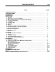
TABLE OF CONTENTS TOPIC PUMP IDENTIFICATION . . . . . . . . . . . . . . . . . . . . . . . . . . . . . . . . . . . . . . . STORAGE OF PUMPS . . . . . . . . . . . . . . . . . . . . . . . . . . . . . . . . . . . . . . . CAUTION NOTES . . . . . . . . . . . . . . . . . . . . . . . . . . . . . . . . . . . . . . . . . . INTRODUCTION. . . . . . . . . . . . . . . . . . . . . . . . . . . . . . . . . . . . . . . . . . . . INSTALLATION 1. General . . . . . . . . . . . . . . . . . . . . . . . . . . . . . . . . . . . .
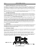
PUMP IDENTIFICATION PAGE 1 PUMP IDENTIFICATION Congratulations! You are the owner of one of the finest pumps commercially available. If you give it the proper care as outlined and recommended by this manual, it will provide you with reliable service and long life. 441 & 491 SPLIT CASE PUMPS Your Aurora Model 441 & 491 is a Split Case Pump, meaning the casing is split along the horizontal centerline.
PAGE 2 STORAGE OF PUMPS AND CAUTION NOTES THESE INSTRUCTIONS APPLY TO THE PUMP ONLY. THEY ARE INTENDED TO BE GENERAL AND NOT SPECIFIC. IF YOUR OPERATING CONDITIONS EVER CHANGE, ALWAYS REFER TO THE FACTORY FOR REAPPLICATION. ALWAYS REFER TO THE MANUALS PROVIDED BY MANUFACTURERS OF THE OTHER EQUIPMENT FOR THEIR SEPARATE INSTRUCTIONS.
INTRODUCTION AND INSTALLATION PAGE 3 INTRODUCTION This manual contains information which is the result of carefully conducted engineering and research efforts. It is designed to supply adequate instructions for the safe and efficient installation, operation maintenance of your pump. Failure or neglect to properly install, operate or maintain your pump may result in personal injury, property damage or unnecessary damage to the pump.
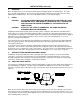
PAGE 4 3. INSTALLATION (continued) MINIMUM SUBMERGENCE OF SICTION PIPE AND PIT DESIGN For installations where the pump draws fluid from a sump, the hydraulic characteristics of the pump, the suction inlet submergence and NPSH must be considered. Generally, it is required that an evenly distributed flow of non-aerated water be supplied to the suction bell.
INSTALLATION (continued) 7. PAGE 5 GROUTING When the alignment is correct, the unit should be grouted using high grade non-shrinking grout. The entire base should be filled with grout. Be sure to fill all gaps and voids. Allow the grout to fully cure before firmly tightening the foundation bolts. Then recheck the alignment before connecting the piping. 8.
INSTALLATION (continued) PAGE 6 PUMP MODEL (PUMP SIZE) Centerline of shaft to oil level NOTE: BEARING HOUSING OIL LEVEL CHART 4-441-11A/C 3-441-9A/C 4-441-14C 2-441-8A 4-441-8A 5-441-14A 6-441-12A 3/4" 7/8" 1-3/16" 5-441-18A 6-441-14A/C 6-441-18C 8-441-14A 5-441-11A 6-441-19A 8-441-18A 10-441-20 1-1/2" 1-13/16" For Fire Pumps, the Model designation changes from “441” to “491.
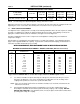
INSTALLATION (continued) PAGE 7 FIGURE 3 COUPLING ALIGNMENT 11. FINAL COUPLING ALIGNMENT (continued) C Check the angular alignment with a micrometer or caliper. Measure from the outside of one flange to the outside of the other at intervals around the periphery of the coupling. Determine the maximum and minimum dimensions. DO NOT ROTATE THE COUPLING. The difference between the maximum and minimum dimensions should not exceed the figure shown under “Angular” in the preceding table.
PAGE 8 INSTALLATION continued) 14. MECHANICAL SEALS CAUTION: DRY OPERATION OF THE PUMP MAY CAUSE DAMAGE TO THE MECHANICAL SEAL AND IMPELLER. Model 441 pumps can be supplied with optional single face mechanical shaft seals. Mechanical seals are installed and adjusted in the factory and require no further adjustments in the field. For further information, refer to the seal manufacturer’s instructions.
OPERATION PAGE 9 Because variations exist in both the equipment used with these pumps and in the particular installation of the pump and driver, specific operating instructions are not within the scope of this manual. However, there are general rules and practices that apply to all pump installations and operation. CAUTION: BEFORE STARTING OR OPERATING THE PUMP, READ THIS ENTIRE MANUAL, ESPECIALLY THE FOLLOWING INSTRUCTIONS: A. BEFORE STARTING THE PUMP, INSTALL CLOSED GUARDS AROUND THE COUPLING. B.
PAGE 10 OPERATION (continued) 3. STARTING THE PUMP A. After the pump is primed, and with the discharge valve closed and the suction valve open, start the driver according to the driver manufacturer’s instructions. Open the discharge valve slowly to prevent water hammer. After the pump has been started, check bearing temperatures, packing box lubrication and operation and pump noise level for a period of several hours. B. C.
MAINTENANCE 1.
MAINTENANCE (continued) PAGE 12 2. INSPECTIONS AND PREVENTIVE MAINTENANCE REQUIREMENTS To assure satisfactory operation of the pump, daily inspections and periodic maintenance are required. We suggest that an inspection and maintenance log be kept and that the inspector immediately report any problems. A guide for preventive maintenance for normal applications is given below. Unusual applications, with abnormal heat, moisture, dust, etc. may require more frequent inspections and service.
MAINTENANCE (continued) PAGE 13 3. BEARING LUBRICATION (continued) Check the oiler setting periodically to be sure it is correct. Refer to the following table for the correct setting. RECOMMENDED OILS: The oil used should be non-detergent type containing rust and oxidation inhibitors, supplied by a reputable manufacturer.
MAINTENANCE (continued) PAGE 14 5. PACKING REPLACEMENT (continued) 2-441-8A PACKING BOX Sleeve O.D. Packing Box I.D. Packing Box Depth PACKING SIZE Qty.
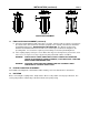
MAINTENANCE (continued) PAGE 15 6. PUMP DISASSEMBLY (continued) E. Remove the capscrews (159D) that secure the bearing housing covers (159) to the bearing housings and remove the housings from the rotating assembly. F. Remove the outer snap ring (345) from the outboard bearing end of the rotating assembly, and use a wheel/bearing puller to remove the outboard (168) and inboard (163) bearings.
MAINTENANCE (continued) PAGE 16 7. PUMP ASSEMBLY CAUTION: READ THIS ENTIRE PROCEDURE BEFORE CONTINUING. Following are step-by-step instructions for assembly of the pump and are essentially the reverse order of the instructions for disassembly. A. Thoroughly clean all parts to remove oil, grease and foreign material. Inspect for wear or damage and replace if required. Remove all parts to a clean and dust-free location for assembly.
MAINTENANCE (continued) PAGE 17 7. PUMP ASSEMBLY (continued) Sleeves Secured With Loctite Only: Clean the shaft, the bore of the sleeves and the bore of the impeller with Loctite “Safety Solvent #75559. Install the impeller key in the shaft and coat the impeller area on the shaft with Loctite 601. Press the impeller onto the shaft, centering it between the shoulders as shown in Figure 5. Coat the shaft on the shaft/sleeve fit and the bore of the sleeves with Loctite 601.
PAGE 18 MAINTENANCE (continued) 7. PUMP ASSEMBLY (continued) M. Attach the bearing housings to the lower casing using the appropriate dowel pins (158A) and capscrews (158B). CAUTION: BE SURE BEARING HOUSING/CASING MATING SURFACES ARE CLEAN AND FREE FROM BURRS, AS THIS WILL AFFECT THE ALIGNMENT OF THE ROTOR/CASING. N. Inspect the upper casing (3) to assure that the water passage is clean and free from foreign material.
REPAIR PARTS PAGE 19 ORDERING PARTS There are a variety of options available for this pump. When ordering parts, give the pump serial number, size and figure number and a complete description and item number of each part. Refer to the drawings and parts list in the back of this manual. You should order parts from your local Aurora Pump distributor. Consult your local telephone yellow pages for the office nearest you.
PAGE 20 NOTES
NOTES PAGE 21
PAGE 22 NOTES
SECTIONAL DRAWING Figure 6 STANDARD CONSTRUCTION PAGE 23
PAGE 24 SECTIONAL DRAWINGS Figure 7 REF. DESCRIPTION NO.