
User's Manual


PAGE 6 INSTALLATION (continued)
BEARING HOUSING OIL LEVEL CHART
4-441-11A/C 5-441-18A 5-441-11A
PUMP MODEL 3-441-9A/C 4-441-14C 6-441-14A/C 6-441-19A
(PUMP SIZE) 4-441-8A 5-441-14A 6-441-18C 8-441-18A
6-441-12A 8-441-14A 10-441-20
Centerline of shaft to oil level 3/4" 7/8" 1-3/16" 1-1/2" 1-13/16"
2-441-8A
NOTE: For Fire Pumps, the Model designation changes from “441” to “491.”
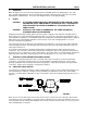
Adjust the oil level, if necessary, by loosening the setscrews on the side of the dust cap, raising the bottle and
tightening the screws. Refer to the oiler manufacturer’s instructions for more specific details.
11. FINAL COUPLING ALIGNMENT
The alignment of the coupling must be carefully checked during installation and as the last step before starting
the pump. If realignment is required, the piping should be disconnected first. After aligning, reconnect the
piping in accordance with the previous instructions and again recheck the alignment.
A flexible coupling must not be used to compensate for misalignment resulting from poor installation or
temperature changes.
Aurora Pumps are supplied with several different types of commercial couplings. The following instructions
apply to units supplied with Woods couplings. If your unit has a different brand coupling, the manufacturer’s
instructions should be obtained before proceeding.
NOTE: FOR MAXIMUM LIFE, KEEP MISALIGNMENT VALUES AS NEAR TO ZERO AS POSSIBLE.
MAXIMUM ALLOWABLE MISALIGNMENT – WOODS COUPLINGS (Dimensions in inches)
Sleeve Types E & N Type H
Size Parallel Angular Parallal Angular
4 1/2 .005 .021 - -
5 3/4 .007 .028 - -
6 7/8 .007 .035 .005 .008
7 1 .010 .040 .006 .010
8 1-1/8 .010 .047 .007 .012
9 1-7/16 .012 .054 .008 .014
10 1-5/8 .012 .064 .010 .016
11 1-7/8 .016 .075 .011 .018
12 2-5/16 .016 .087 .012 .021
13 2-11/16 .020 .092 .015 .025
14 3-1/4 .022 .121 .017 .030
16 4-1/4 .031 .165 - -
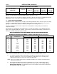
"G" Dimension
The coupling Type is printed on the sleeve.
* Type H sleeves SHOULD NOT be used as direct replacements for EPDM or Hytrel sleeves.
A. Use a blunt screwdriver to slip the wire ring out of the groove and remove the two-piece sleeve.
Check the “G” dimension. If it is not as shown in the preceding table, loosen one flange of the
coupling and reposition it to achieve the specified “G” dimension.
NOTE: On a sleeve bearing electric motor, the armature should be at its electrical center when the “G”
dimension is measured.
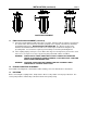
B. Check parallel misalignment by placing a straightedge across the two coupling flanges and
measuring the maximum offset at various points around the periphery of the coupling. DO NOT
ROTATE THE COUPLING. If the maximum offset exceeds the figure shown under “Parallel” in the
preceding table, realign the coupling.