® AURORA Wind Inverters INSTALLATION AND OPERATION MANUAL Model number: PVI-6000-OUT-UK-W Rev. 1.
User Manual (PVI-6000-OUTD-UK-W Rev.1.0) Page 2 of 74 REVISION TABLE Document Revision Author Date Change Description Rev 1.0 Federico Mastronardi Dec. 5, 2008 First emission SAVE THESE INSTRUCTIONS! IMPORTANT SAFETY INSTRUCTIONS POWER-ONE: Reproduction and disclosure, even partially, of the contents of this manual are strictly forbidden without prior authorization of PowerOne.
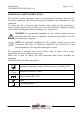
User Manual (PVI-6000-OUTD-UK-W Rev.1.0) Page 3 of 74 IMPORTANT SAFETY INSTRUCTIONS This manual contains important safety and operational instructions that must be accurately understood and followed during the installation and maintenance of the equipment. To reduce the risk of electrical shock hazards, and to make sure the equipment is safely installed, special safety symbols are used in this manual to highlight potential safety hazard and important safety information.
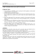
User Manual (PVI-6000-OUTD-UK-W Rev.1.0) Page 4 of 74 USEFUL INFORMATION AND SAFETY STANDARD INTRODUCTION ¾ The installation of AURORA must be performed in full compliance with national and local standards and regulations. ¾ AURORA has no spare parts to replace. For any maintenance or repair, please, contact the nearest authorized repair centre. Please contact your reseller if you need to know the nearest authorized repair facility.
User Manual (PVI-6000-OUTD-UK-W Rev.1.0) Page 5 of 74 ASSEMBLY Devices shall be assembled and cooled according to the specifications mentioned in the corresponding documents. In particular, during transportation and handling, parts shall not be bent and/or the insulation distances shall not be changed. There should be no contact between electronic parts and connection terminals. Electrical parts must not be mechanically damaged or destroyed (potential health risk).
User Manual (PVI-6000-OUTD-UK-W Rev.1.0) Page 6 of 74 PVI-6000-OUTD-UK-W This document applies to the above-mentioned inverters, only. Fig.
User Manual (PVI-6000-OUTD-UK-W Rev.1.0) Page 7 of 74 CONTENTS 1 INTRODUCTION .......................................................................10 2 SYSTEM DESCRIPTION ..........................................................11 2.1 KEY ELEMENTS OF A WIND ENERGY SYSTEM: “WIND TURBINE” AND “GENERATOR” .................................................................................................... 11 2.2 DATA MONITORING AND TRANSMISSION ................................................... 14 2.
User Manual (PVI-6000-OUTD-UK-W Rev.1.0) Page 8 of 74 5.5.2 Error messages......................................................................................43 5.5.3 First phase - electric parameter monitoring .........................................44 5.5.4 Main menu.............................................................................................47 5.5.5 Statistics ................................................................................................47 5.5.5.1 Lifetime .........
User Manual (PVI-6000-OUTD-UK-W Rev.1.0) 8 Page 9 of 74 TECHNICAL FEATURES.........................................................69 8.1 8.2 8.3 8.4 8.5 INPUT VALUES .......................................................................................... 69 OUTPUT VALUE ........................................................................................ 70 GRID PROTECTION CHARACTERISTICS ....................................................... 70 GENERAL CHARACTERISTICS ...........................
User Manual (PVI-6000-OUTD-UK-W Rev.1.0) 1 Page 10 of 74 INTRODUCTION This document contains technical description of AURORA Wind inverters. It is intended to provide the installers and users with all the necessary information about installation, operation, and use of AURORA Wind inverters.
User Manual (PVI-6000-OUTD-UK-W Rev.1.0) 2 Page 11 of 74 SYSTEM DESCRIPTION The AURORA inverter is capable of feeding power to the grid converting the power generated by a wind turbine. The wind turbine (using a generator) converts the mechanical energy from wind into the 3-phase AC voltage. The voltage and frequency of the AC generated by the wind turbine are variable and depend on the wind speed.
User Manual (PVI-6000-OUTD-UK-W Rev.1.0) Page 12 of 74 B) The resulting DC output is connected to the AURORA input and converted into AC power with the appropriate voltage and frequency to be exported to the grid. Wind Turbine Generator Fig. 2 - Wind Turbine – Generator WARNING: The DC voltage input to the inverter shall not exceed 600Vdc for any reason, in order to avoid damage to the equipment.
User Manual (PVI-6000-OUTD-UK-W Rev.1.0) Page 13 of 74 Wind Turbine Generator AC Grid Rectifier/ Interface DC Disconnect (2-pole) DC Voltage AC Voltage AC disconnect (3-pole) Fig.
User Manual (PVI-6000-OUTD-UK-W Rev.1.0) 2.2 Page 14 of 74 Data monitoring and transmission In system with more than one inverter, remote monitoring can be implemented through a sophisticated communication system based on an RS-485 serial interface. A USB port is available in the inverter to facilitate access during installation. An optional AURORA Easy-Control system is also available for remote monitoring via the Internet, analogue modem or GSM digital modem. 2.
User Manual (PVI-6000-OUTD-UK-W Rev.1.0) Page 15 of 74 The block diagram shows an AURORA PVI-6000-OUTD with the two input DC-DC converters; in the Wind version the 2 converters are always connected in parallel. Thanks to its high efficiency and excellent thermal design, the AURORA inverter provides maximum power operation in a broad range of ambient temperatures. The inverter is controlled by two independent DSPs (Digital Signal Processors) and one central microprocessor.
User Manual (PVI-6000-OUTD-UK-W Rev.1.0) ¾ Page 16 of 74 automatic power limit based on internal temperature monitoring to avoid overheating (heat sink temperature ≤70°C [158°F]).
User Manual (PVI-6000-OUTD-UK-W Rev.1.0) 3 Page 17 of 74 INSTALLATION WARNING: The electrical installation of AURORA must be performed in compliance with applicable local and national standards and laws. WARNING: The connection of AURORA to the electrical distribution grid must be performed only after receiving authorization from the utility that operates the grid 3.1 Package Inspection NOTE: The shipper delivered your AURORA inverter to the carrier safely packaged and in perfect condition.
User Manual (PVI-6000-OUTD-UK-W Rev.1.0) 3.2 Page 18 of 74 Inspecting package contents Description Inverter AURORA Bag containing: 6.3x70 screws 3 pc. 3 SX10 wall anchors 3 pc. Torx20 wrench 1 pc M6x10 screw 1 pc d.
User Manual (PVI-6000-OUTD-UK-W Rev.1.0) 3.3 Page 19 of 74 Selecting the place of installation The installation place should be selected based on the following considerations: ¾ Height from ground level should be enough to ensure that display and status LEDs are easy to read. ¾ Select a well ventilated place sheltered from direct sun radiation. Choose a place that allows unobstructed airflow around the unit.
User Manual (PVI-6000-OUTD-UK-W Rev.1.0) 3.4 Page 20 of 74 Wall mounting AURORA should be mounted in a vertical position as shown in Fig.6. The package includes a hardware kit with three 6.3x70 steel screws and 3 SX10 wall anchors for installation of a metal bracket to a masonry wall. Screws and wall anchors can be installed using 3 of the 5 holes available on the bracket (reference part C in the pictures below).
User Manual (PVI-6000-OUTD-UK-W Rev.1.0) Page 21 of 74 Part.B Part.A Fig.6 -. AURORA wall mounting Part.D Part.C NOTE: Ensure that the AURORA inverter is not exposed to direct sun radiation or other external heat sources, including the units installed underneath it (see Fig. 7). If several inverters are stacked up, the heat generated by the inverters placed at the bottom of the stack could cause ambient temperature to rise and affect the operation of the inverters in the upper rows.
User Manual (PVI-6000-OUTD-UK-W Rev.1.0) Page 22 of 74 RECOMMENDED ARRANGEMENT Fig.7 - Recommended installation of AURORA inverters NOTE: Although tilted mounting is allowed (see Fig. 8) it will cause increased power dissipation and may result in output power derating. WARNING: Unit surface may become very hot during operation. DO NOT touch unit surface to avoid burns. NO Derating -5° Derating 0° Derating 5° Derating Fig.
User Manual (PVI-6000-OUTD-UK-W Rev.1.0) 3.5 Page 23 of 74 Before performing electrical connections WARNING: Electrical connections shall be performed only after the AURORA inverter is securely mounted to the wall. WARNING: The connection of the AURORA inverter to the electrical distribution grid must be performed by qualified operators and only after receiving authorization from the utility that operates the grid.
User Manual (PVI-6000-OUTD-UK-W Rev.1.0) Page 24 of 74 Rete Generator AC Disconnect switch AC Disconnect switch 3-phase Max. Rating 40A/400Vac Loads Max. Rating 40A/240Vac Rectifier/ Wind Interface Fig.9 - Wiring diagram WARNING: When disconnecting the AURORA inverter, always open the AC disconnect switches to disconnect the inverter from the grid and from the generator. Wait until the LEDs on the front panel turn off before unplugging the multiple contact connections from the DC input.
User Manual (PVI-6000-OUTD-UK-W Rev.1.0) ¾ Page 25 of 74 Cable gland for DC connection to the rectifier. Fig. 10 - Connectors on the bottom of the inverter and their labels ¾ WARNING: When making the electrical connections follow the procedure exactly to avoid exposure to dangerous voltages. Each step of the procedure is explained in the following paragraphs. To disconnect the AURORA inverter, perform steps 1/6 and 2/6 and then disconnect the AC and DC connectors.
User Manual (PVI-6000-OUTD-UK-W Rev.1.0) 3.6 Page 26 of 74 Electrical Connections Step 1/6: Open the AC grid disconnect switch Step 2/6: Open the Wind Generator AC disconnect breaker. Step 3/6: Unscrew the 4 screws to open the front panel Step 4/6: Connect the inverter to the AC grid disconnect switch WARNING: Use suitable low-impedance cables to connect the inverter to the AC disconnect switch.
User Manual (PVI-6000-OUTD-UK-W Rev.1.0) Step 5/6: Page 27 of 74 Connect AURORA to the Rectifier/Wind Interface Box WARNING: Prior to connecting the AURORA inverter to the rectifier check, using a proper meter, that the polarity and the voltage value between the positive and negative terminal are correct. The output voltage polarity from the rectifier should match the “+” and “-” symbols. Referring to Fig.
User Manual (PVI-6000-OUTD-UK-W Rev.1.0) Page 28 of 74 Wind frequency input Fig.12 - DC section cables Power-One recommends using the Wind Interface box p/n PVI-7200-Wind-InterfaceUS. Refer to the Aurora Wind Interface User Manual for more details. 3.7 Step 6/6 (optional): Connection of the frequency signal from the wind turbine.
User Manual (PVI-6000-OUTD-UK-W Rev.1.0) Page 29 of 74 3 1 4 2 Fig.13 - AURORA with front panel After replacing the front panel, tighten the screws to 1.5 Nm (13.2 in-lbs) to ensure proper sealing. 3.9 Replacing the CR2032 lithium battery WARNING: This component should only be replaced by qualified personnel. The AURORA inverter has a CR2032 lithium battery. When the battery is nearing the end of its life, a corresponding message appears on the LCD display.
User Manual (PVI-6000-OUTD-UK-W Rev.1.0) 3.10 Page 30 of 74 Replacing the memory All energy output logs are stored in this memory. If you need to replace the inverter, the memory can be removed from the old unit and placed into the new inverter. This way, you will retain all system logs and keep saving future daily logs into the same memory (see Fig. 15) Fig. 15 - Inverter memory WARNING: This component should only be replaced by qualified personnel.
User Manual (PVI-6000-OUTD-UK-W Rev.1.0) 4 Page 31 of 74 START UP WARNING: Do not place any items on AURORA during operation. WARNING: Do not touch the heat sink when the inverter is operating, as some parts may be hot and cause burns. Start-up procedure: 1) Switch the AC breaker ON. If the speed of the turbine is high enough to generate at least 50V DC on the rectifier output, the AURORA inverter will turn on (the display lights on).
User Manual (PVI-6000-OUTD-UK-W Rev.1.0) 5 5.1 Page 32 of 74 MONITORING AND DATA TRANSMISSION User’s Interface Mode WARNING: The RS-485 cable must provide at least 600V insulation. The AURORA inverter operates automatically and needs no particular supervision. If the turbine speed is not enough to generate power for the grid, the inverter disconnects automatically and goes into the standby mode.
User Manual (PVI-6000-OUTD-UK-W Rev.1.0) Fig.
User Manual (PVI-6000-OUTD-UK-W Rev.1.0) 5.2 Page 34 of 74 Available Data AURORA provides two types of data that can be collected using the suitable interface software. 5.2.1 Real-time operational data Real-time operational data can be transmitted on demand through the communication lines and are not stored by the inverter. The AURORA Communicator software is available on the installation CD and may be used to transmit data to a PC (check for the latest version on www.power-one.com).
User Manual (PVI-6000-OUTD-UK-W Rev.1.0) 5.2.
User Manual (PVI-6000-OUTD-UK-W Rev.1.0) 1 2 3 Page 36 of 74 ESC DOWN UP Fig.
User Manual (PVI-6000-OUTD-UK-W Rev.1.
User Manual (PVI-6000-OUTD-UK-W Rev.1.0) Page 38 of 74 G Y R 1) Standby mode AURORA is waiting for higher voltage on the input; this occurs when input voltage is too low to feed the inverter. G Y 2) Initialization and grid check Initialization in progress: input power is sufficient to feed the inverter; AURORA is verifying start-up conditions (for instance: input voltage value, insulation resistance value, etc.) and grid monitoring routine has been launched.
User Manual (PVI-6000-OUTD-UK-W Rev.1.0) G Y R G Y R 5.4 Page 39 of 74 6) RS-485 address setup indication During installation, the yellow LED will keep flashing until the address is acknowledged. For further information about entering the address, refer to section 6.3. 7) Grid disconnection If a grid failure event occurs while the system is operating, the yellow LED turns on continuously. Messages and Error Codes The system status is identified through message or error signals appearing on the LCD.
User Manual (PVI-6000-OUTD-UK-W Rev.1.0) Page 40 of 74 Message Error code Error type Description Sun Low W001 // Input Voltage under threshold Input voltage under threshold (when off) Input OC // E001 Input Overcurrent Input UV W002 // Input Undervoltage Input OV // E002 Input Overvoltage Int.Error // E003 No parameters Bulk OV // E004 Bulk Overvoltage Int.Error // E005 Communication Error Out OC // E006 Output Overcurrent Int.
User Manual (PVI-6000-OUTD-UK-W Rev.1.0) Page 41 of 74 Message Error code Error type Description Int.Error // E023 Dc-Injection Error Grid OV W004 // Output Overvoltage Grid UV W005 // Output Undervoltage Grid OF W006 // Output Overfrequency Grid UF W007 // Output Underfrequency Z Grid HI W008 // Z grid out of range Int.Error // E024 Unkown Error – --------- // E025 Riso Low (Log Only) Int.Error // E026 Vref Error Int.Error // E027 Vgrid Measures Fault Int.
User Manual (PVI-6000-OUTD-UK-W Rev.1.0) 5.5 Page 42 of 74 Display LCD 5.5.1 Connection of system to the grid The two-line Liquid Crystal Display is located on the front panel and shows: 9 Inverter operating status and statistics; 9 Service messages for operator; 9 Error messages and fault indications. During regular operation, the display will cycle through available data.
User Manual (PVI-6000-OUTD-UK-W Rev.1.0) Page 43 of 74 4) Shows instant output voltage value and within/outside range status. Vgrid In range 197,8 V 5) Shows instant output frequency value and within/outside range status.
User Manual (PVI-6000-OUTD-UK-W Rev.1.0) 5.5.3 Page 44 of 74 First phase - electric parameter monitoring A FEW POINTERS ON DISPLAY KEY OPERATION: During regular operation, the display will cycle through available data. The display shows a different screen every 5 seconds, screens may be scrolled manually by pressing the UP and DOWN buttons next to the display. Pressing the ESC key (right next to the display) calls back the previous menu. Fig.20 Fig.
User Manual (PVI-6000-OUTD-UK-W Rev.1.0) Page 45 of 74 4A) E-tot E-par ------------0 KWh E-tot : Lifetime energy output (since first installation) E-par : Partial energy output (during selected period) 5A) P-out T-inv 0 - W °C P-out : Measured instant output power The second line of the display shows the higher of two temperatures: T-inv: inverter heatsink temperature T-boost: heatsink temperature 6A) Ppk W Ppk Day ………...
User Manual (PVI-6000-OUTD-UK-W Rev.1.0) Page 46 of 74 9A) Vin I in 0V 0.0 A Pin 0W Vin: input voltage value Iin1: Instant input current value 10A) Pin: Measured instant input power 11A) Riso Ileak 0.0 Mohm 73 mA Riso: Measured insulation resistance. Unlike the parameters discussed above, this is not an instant value but a measurement taken one time during inverter start-up.
User Manual (PVI-6000-OUTD-UK-W Rev.1.0) 5.5.4 Page 47 of 74 Main menu When the grid connection sequence described above and all electrical parameter checks are completed, other screens become available. These screens let you monitor inverter operation. Pressing the ESC button gives access to 3 new screens: Statistics Settings Info - A FEW POINTERS ON DISPLAY KEY OPERATION: - Press the UP and DOWN buttons to scroll through items. - Press the ESC button to go back to the previous session (see sect. 5.
User Manual (PVI-6000-OUTD-UK-W Rev.1.0) 5.5.5.1 Page 48 of 74 Lifetime Select Lifetime to view the following information: Time E-tot Val. CO2 h KWh EUR Kg Time: Lifetime operation time E-tot : Lifetime energy output Val. : Money earned CO2: CO2 saving compared to fossil fuel 5.5.5.2 Partial Select Partial to view the following information: Time E-par Ppeak Val.
User Manual (PVI-6000-OUTD-UK-W Rev.1.0) Page 49 of 74 5.5.5.3 Today Select Today to view the following information: E-tod Ppeak Val. CO2 KWh W EUR Kg E-tod: Total energy output during the day Ppeak: Peak power achieved during the day Val: Money earned during the day CO2: CO2 saving compared to fossil fuels during the day 5.5.5.4 Last 7 days Select Last 7 days to view the following information: E-7d Val. CO2 KWh EUR Kg E-7d: Total energy output during the last 7 days Val.
User Manual (PVI-6000-OUTD-UK-W Rev.1.0) Page 50 of 74 5.5.5.6 Last 30 Days Select Last 30 Days to view the following information: E-30d Val. CO2 KWh EUR Kg E-30d: Total energy output during the last 30 days Val.: Money earned during the last 30 days CO2: CO2 saving compared to fossil fuels during the last 30 days 5.5.5.7 Last 365 Days Select Last 365 Days to view the following information: E-365d Val. CO2 KWh EUR Kg E-365d: Total energy output during the last 365 days Val.
User Manual (PVI-6000-OUTD-UK-W Rev.1.0) Page 51 of 74 To set days: ¾ Press DOWN to scroll numbers backwards (from 31 to 1) ¾ Press UP to scroll numbers from 1 to 31 To set the month: ¾ Press DOWN to scroll months from December to January ¾ Press UP to scroll months from January to December If set dates are inconsistent, the display alerts the user to the problem: Data err 5.5.6 Settings Select SETTING from the Main menu (sect. 5.5.
User Manual (PVI-6000-OUTD-UK-W Rev.1.0) Page 52 of 74 The display has 2 lines; use the buttons on the side of the display to scroll through items or open the corresponding submenus as described in section 5.5.4 A FEW POINTERS ON DISPLAY DATA READING. An arrow on left side of the display highlights your current selection. When an item is selected, press ENTER to open the submenu. 5.5.6.1 Address This function is used to set addresses for communication with inverters connected in the system on RS-485 line.
User Manual (PVI-6000-OUTD-UK-W Rev.1.0) Page 53 of 74 ON: Light is always on OFF: Light is always off AUTO: Automatic light setting. It turns on every time a button is pressed and stays on for 30 seconds then gradually turns off. 2) Contrast: display light contrast Available display light tones from 0 to 9. Press UP and DOWN to scroll through numbers and press ENTER to select. 3) Buzzer: key tone setting Selecting: ON: key tone is on OFF: key tone is off 5.5.6.
User Manual (PVI-6000-OUTD-UK-W Rev.1.0) Page 54 of 74 5.5.6.6 Time This function allows time and date setting. Time 14:21 Date 17 May 2006 5.5.6.7 Language It is possible to set the national language or English. English Italiano 5.5.6.8 START UP voltage Start-up voltage can be set according to the characteristics of the wind turbine/generator system. Voltage range can be 50V to 350V. The default setting is 50V. This parameter can be changed by means of the display keys. VStart 50V 5.5.6.
User Manual (PVI-6000-OUTD-UK-W Rev.1.0) Page 55 of 74 The display has 2 lines; use the buttons on the side of the display to scroll through items or open the corresponding submenus. An arrow on the left side of the display highlights your current selection. When an item is selected, press ENTER to open the submenu. As soon as a test is selected, the display shows Test in process ……………….. During the test the display gives test progress indication.
User Manual (PVI-6000-OUTD-UK-W Rev.1.0) Page 56 of 74 Fig. 22 - Alarm contacts terminal block This function can activate two alarm modes. Press ENTER to open the relevant submenu: Production Fault An arrow on the left side of the display highlights your current selection. When an item is selected, press ENTER to confirm activation of chosen mode. PRODUCTION: Relay is only activated when the inverter is connected to the grid (contact closing across terminals “N.O.
User Manual (PVI-6000-OUTD-UK-W Rev.1.0) Page 57 of 74 Manual ON and OFF input is read on inverter digital input. When set to OFF, the display will cycle through the following screens: Remote OFF Waiting Rem.ON… ….to restart 5.5.6.12 UV Prot.time This function is used to set the inverter connection time after the input voltage drops below the undervoltage protection threshold that is set at 40V. For example: if UV Prot.
User Manual (PVI-6000-OUTD-UK-W Rev.1.0) Page 58 of 74 Select COMPOSE MESSAGE. It is now possible to write the first line of the message. Message row 1: ---------------- The maximum number of characters is 16.
User Manual (PVI-6000-OUTD-UK-W Rev.1.0) 5.5.7 Info This menu is used to display all AURORA data: ¾ Part No. (part number) ¾ Serial No.
User Manual (PVI-6000-OUTD-UK-W Rev.1.
User Manual (PVI-6000-OUTD-UK-W Rev.1.0) 6 6.1 Page 61 of 74 DATA MONITORING AND COMMUNICATION Connection through RS-485 serial port or RJ12 connector 6.1.1 RS-485 serial port The RS-485 serial port uses a three-wire cable: two wires are for signals and the third one is for ground connection. Cable is routed through the holes located at the bottom of the inverter. The holes are sealed with waterproof plugs (see Fig. 23). Supplied cable glands must be installed in the suitable hole.
User Manual (PVI-6000-OUTD-UK-W Rev.1.0) Page 62 of 74 After passing through the cable gland, cables are connected inside the unit to the RS485 terminal blocks that can be reached by removing the front panel. Refer to p. 3.7 for details on front cover removal and installation. ¾ ¾ Signal wires must be connected to the +T/R and –T/R terminals Ground wire must be connected to the RTN terminal RJ12 #1 RJ12 #2 Fig.24 - Terminals for connection to RS-485 serial line and S2 6.1.
User Manual (PVI-6000-OUTD-UK-W Rev.1.0) Page 63 of 74 RJ12 connectors Pin # Signal Name 1 Not Used 2 +TR 3 +R 4 -TR 5 6 6.1.3 Description + Data Line Required for RS485 communication. Remote OFF Required or Remote OFF chapter 5.5.6.11 for details). control (see - Data Line Required for RS485 communication. Not Used RTN Signal Return Common reference for logical signals.
User Manual (PVI-6000-OUTD-UK-W Rev.1.0) Page 64 of 74 The following diagram shows how to connect multiple units in a daisy chain configuration. Fig. 25 - Daisy chain connection of multiple inverters NOTE: When using a RS-485 link there can be up to 248 inverters connected on the same link.
User Manual (PVI-6000-OUTD-UK-W Rev.1.0) 6.2 Page 65 of 74 Serial connection with USB port Serial connection through a USB port allows connection of a single inverter to a personal computer equipped with a USB 2.0 interface and dedicated software supplied by Power-One. PC-inverter connection cable is a standard USB 2.0 cable, 16 feet long, with terminals of the A and B type. Just remove the waterproof plug located on AURORA side to make the connection (see Fig. 26). Fig.
User Manual (PVI-6000-OUTD-UK-W Rev.1.0) 6.3 Page 66 of 74 Measurement Accuracy The following table shows measurement accuracy fro each value monitored and reported by the AURORA inverter: Name Unit Resolution Display Value Accuraccy Input voltage PV N°1 VP1 Vdc 1V 600mV 2% Input voltage PV N°2 VP2 Vdc 1V 600mV 2% Input current PV N°1 IP1 Adc 0.1A 25mA 2% Input current PV N°2 IP2 Adc 0.
User Manual (PVI-6000-OUTD-UK-W Rev.1.0) 7 Page 67 of 74 TROUBLESHOOTING AURORA inverters comply with standards set for grid-tied operation, safety and electromagnetic compatibility. Before being delivered, the product has been successfully subjected to several tests to check operation, protections, performance and durability. All these tests, together with the system ensuring Power-One quality, guarantee optimal operation of the AURORA inverters.
User Manual (PVI-6000-OUTD-UK-W Rev.1.
User Manual (PVI-6000-OUTD-UK-W Rev.1.0) 8 Page 69 of 74 TECHNICAL FEATURES 8.1 Input Values WARNING: The output voltage from the rectifier shall always be less than 600VDC. WARNING: Inverter is provided with a linear output power derating depending on the input voltage, starting from 530 Vdc (100% output power) to 580 Vdc (0% output power) Description Max.
User Manual (PVI-6000-OUTD-UK-W Rev.1.0) 8.2 Page 70 of 74 Output Value Description Nominal output power Grid voltage, maximum range Grid voltage, nominal Grid voltage, operating range Grid frequency, maximum range Grid frequency, nominal Grid frequency, operating range Value PVI – 6000 – OUTD – UK -W 6,000 W 180 to 264 Vac 230 Vac 82% to 115% of nominal voltage (188.6 to 264Vac for V=230Vac) 47 to 63 Hz 50 Hz 49.72 to 50.28 Hz Nominal output current 26 Arms Max.
User Manual (PVI-6000-OUTD-UK-W Rev.1.0) 8.4 Page 71 of 74 General characteristics Description Maximum efficiency Value PVI – 6000 – OUTD-UK-W 97% (>96 Euro) Internal consumption during standby <8W Internal consumption during nighttime <1W Operating ambient temperature -25°C to +60°C (*) Casing protection rating IP65 / Nema 4X Audible noise with internal fan on < 50 dbA @ 1m Size (height x width x depth): Weight Relative Humidity 29.1” x 12.8” x 7.5” 59.
User Manual (PVI-6000-OUTD-UK-W Rev.1.0) 8.5 Page 72 of 74 Power Derating In order to ensure reliable operation under different ambient and loading conditions, the AURORA inverters automatically decrease the output power as a function of the temperature and input voltage. Power reduction due to environmental conditions Power reduction and temperature at which it occurs depend on many parameters other than ambient temperature, such as input voltage, grid voltage, etc.
User Manual (PVI-6000-OUTD-UK-W Rev.1.
User Manual (PVI-6000-OUTD-UK-W Rev.1.