
User Manual

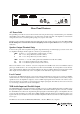

Rear Panel Features
AC Power Inlet
The 3 pin IEC power inlet is located on the bottom left of the rear panel and accepts a standard mains power lead fitted
with an IEC connector. Before plugging in a power lead, please check the rear panel of the amplifier to ensure that the
voltage label shows the correct AC operating voltage for your part of the world.
The inlet is equipped with an in-built AC fuse holder fitted with a 6 Amp slow blow fuse plus a spare fuse. Please ensure
that the mains power cord is disconnected before attempting to check or replace this fuse. Power consumption is 400
watts (max).
Speaker Output Terminal Strip
Located on the top left of the rear panel are the speaker output terminal strips. A terminal strip is provided for each of the
two amplifiers. Reading from left to right, the connections per terminal strip are:
COM Common or “-” for low impedance speaker loads (4 or 8 ohms).
4 The “+” for 4 ohm speaker loads (use with common)
8 The “+” for 8 ohm speaker loads (use with common)
COM Common or “-” for 70v or 100v speaker loads (maximum load of 80 ohms at 100v)
70 The “+” for 70v line speaker loads (use with common)
100 The “+” for 100v line speaker loads (use with common)
Please ensure that the correct “Common” is used. Low impedance and 70/100v loads can be used simultaneously but
please pay careful attention to the overall speaker load. When used individually, the low impedance load should be 4
ohms or higher while the 100v line load should not fall below 80 ohms per amplifier. When both low impedance and 70/
100v outputs are used simultaneously on the one amplifier, ensure that neither output is loaded to maximum.
Level Control
Located next to the XLR input/output is a recessed screwdriver adjustable level control. One is provided per amplifier
channel. The level control is an input attenuation control normally used to match the amplifier to a wide variety of input
signals. In essence, the amplifier is designed to receive a 700mv input signal however the level control can be used to
increase the level for lower signals or decrease the level for higher input signals. In normal use, the level control is used
as a ‘set and forget’ master level control for the amplifier.
XLR Audio Input and Parallel Output
The ACM1202P includes both male and female 3 pin XLR connectors per channel. While the female is normally used as
the input to the amplifier, both XLR’s are connected in parallel so either will work. When signal is connected to one XLR,
the other XLR becomes a line level output allowing the input signal to be distributed (split) to other amplifiers. In some
projects, the same input may be looped through to multiple amplifiers using this method. Up to 6 amplifiers can be looped
together without any noticeable loss in level. A distribution amplifier should be used when more than 6 amplifiers need
to be looped.
The XLR’s are wired as follows: Pin 1: Shield. Pin 2: Hot, +, Positive. Pin 3: Cold, -, Negative
AMPLIFIER 2
AMPLIFIER 1
XLR
1 = Ground
2 = + Signal
3 = - Signal
ENGINEERED BY AUDIO TELEX COMM UNICATION S PTY LTD SYDNEY AUSTRALIA
INPUT AMP 1INPUT AMP 2
LEVEL 1LEVEL 2