PROFESSIONAL AUDIO AMPLIFIER OPERATION MANUAL SY2200 SY2400 SY2700 PROFESSION AUD U D IO AMP L
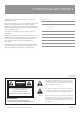
I M P O RTA N T SAF E TY INF ORMATION This operation manual contains important information regarding safety precautions, installation, performance, operation and maintenance of your Synergy-Series power amplifier. You should familiarize yourself with the contents of this manual before operating your amplifier. 1. 2. Save the carton and packing material even if the equipment has 13. Do not block fan intake or exhaust ports. Do not operate equipment arrived in good condition.
INTRODUCTION AND CONTENTS Congratulations on choosing Australian Monitor for your professional amplification requirements. The design of our Synergy-2 Series Audio Power Amplifiers embraces all the aspects of a well designed amplifier. The visual design, mechanical, electrical and sonic parameters, along with our dedicated manufacturing process, have all been optimized to provide a professional tool that exhibits quality, reliability and longevity. The Synergy-2 Series amplifiers are 2 unit (3.
F E AT U R E S > Custom designed, 2RU heavy duty steel chassis. > Signal ground lift switch. > Front carry handles. Rear rack mount ears. > Built in limiter circuit. > Symmetrical layout - even weight distribution. > Stereo or bridged operation > High current power supply. > Binding post and 4 pole speaker output connection > High efficiency toroidal mains transformer. > 1 Watt output indication (2.828 volts). > Efficient front to back cooling. > Output clip indication.
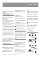
C O N T R O L S , C O N N E C T O R S & I N D I C AT O R S 6 1 Front Panel 1 2 Power Switch Thermal Indicator In the advent of a thermal overload, this LED will turn red, indicating that the internal operating temperature of one or both amplifier channels has exceeded a safe level of operation and the channels will be automatically muted. The fans will continue to run and once the effected channel/s have cooled, they will un-mute and return to normal operation.
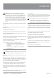
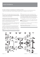
C O N T R O L S , C O N N E C T O R S & I N D I C AT O R S Rear Panel 8 12 10a 14 8 11 10 13 8a Balanced Input A female 3-pin XLR type connector is provided on each input: Pin 1 = Signal Ground; Pin 2 = Hot (non-inverting or in phase); Pin 3 = Cold (inverting or reverse phase). 8a Signal Ground Lift Switch When this switch is engaged it disconnects signal ground from the input connectors on both channels.
I N S TA L L AT I O N Power Requirements Power consumption for your model of the Synergy-2 Series amplifier is indicated on the rear panel for maximum output. Ensure that your mains voltage is the same as the rear panel mains voltage marker (+/- 10%). Mounting Your amplifier is designed for standard 19” rack mounting and occupies 2 EIA rack units (3.5”). The mounting centres are: Vertical: 3.0” (76.2mm) Horizontal: 18.2” (461.2mm) to 18.7” (473.8mm).
I N S TA L L AT I O N Hum Problems Signal Ground-Lift Switch Most equipment is designed for minimum hum when used under ideal conditions. When connected to other equipment, and to a safety earth in an electrically noisy environment, problems may occur. When proper system hook-up has been made, you may still have some hum or hum related noise. This may be due to any of the previously mentioned gremlins.
O P E R AT I O N IMPORTANT: All signal source equipment should be adequately earthed. This not only ensures your safety but everybody else’s as well. Faults can and do occur in mains connected equipment where the chassis can become “live” if it is not properly earthed. In these instances, the fault in a “floating” (ungrounded) piece of equipment will look for the shortest path to ground, which could possibly be your amplifier’s input.
MAINTENANCE Only competent or qualified persons should attempt any service or maintenance of your amplifier. Your Synergy-2 Series amplifier will need minimal maintenance. No internal adjustments need to be made to the unit to maintain optimum performance. To provide years of unhindered operation we suggest a maintenance inspection be carried out on a regular basis, say every 12 months or so.
S P E C I F I C AT I O N S Common Specifications (To all SY2 Amplifiers) Model: SY 2400 Distortion (re 4ohm, 1dB below clip) Output Power 0.1% THD @ 1kHz THD (@ 1kHz) <0.02% IMD SMPTE (60Hz : 7kHz 4:1) <0.03% Input Impedance 20kohms Input Sensitivity 1Vrms Input CMRR >80dB Signal/Noise Ratio A-Weighted >104dB Crosstalk >70dB Slew rate >40 V/µsec 2ohm single channel 2ohm both channels driven 600 525 Stereo Bridged 4ohm 8ohm 350 190 1100 700 Voltage Gain 37.
AUSTRALIA AND NEW ZEALAND w w w. a u s t r a l i a n m o n i t o r. c o m . a u SYDNEY MELBOURNE BRISBANE ADELAIDE PERTH AUCKLAND (NSW & ACT SALES) (VIC & TAS SALES) (QLD SALES) (SA & NT SALES) (WA SALES) (NZ SALES) 149 Beaconsfield Street Silverwater NSW 2128 Private Bag 149 Silverwater NSW 1811 Phone: (02) 9647 1411 Fax: (02) 9648 3698 Email: nsw@audiotelex.com.