
Specifications


CONTROLS, CONNECTORS & INDICATORS
PAGE 5SYNERGY 2 – OPERATION MANUAL
71 2 3 4 5
Power Switch
Press the switch to up for power on and down for
power off. At start-up (turn-on), the input to the
amplifi er is muted for approximately two seconds.
Thermal Indicator
In the advent of a thermal overload, this LED will
turn red, indicating that the internal operating
temperature of one or both amplifi er channels has
exceeded a safe level of operation and the
channels will be automatically muted. The fans
will continue to run and once the effected
channel/s have cooled, they will un-mute and
return to normal operation.
On Indicator
This LED will illuminate blue and indicates that the
amplifi er is on and receiving mains power.
Fault Indicator
This red LED indicates a signifi cant problem with
the amplifi er and the amplifi er should be returned
to an authorised technician for servicing.
Attenuator
Level control for your amplifi er is provided by a
potentiometer on the front panel and indicates
gain. There are 2 controls on all Synergy-2 models.
Each control is labelled for the channel which it
operates.
Status Indicator
This is a dual colour LED which displays the status
of the output stage and displays three levels of
operation.
These levels are:
Below 1 watt (unlit)
1 watt and above (green)
Clipping (red)
The LED will turn green once the output voltage
exceeds 2.828 volts (1 watt re 8 ohms).
The LED will change to red once the output
reaches the threshold of clipping of the amplifi er’s
output stage. The threshold of clipping is referred
to the amplifi er supply rails and alters with
changes in the mains supply, changes in the load
and duty cycle fl uctuations.
The attack and decay time (ballistics), of the status
circuit are those of a Peak Programme Meter
(P.P.M.)
If using this indicator to line up sensitivities, apply
a steady state tone (e.g. slate on a mixing con-
sole). The 1 watt level is the mid-point between
the indicator illuminating and extinguishing green.
NOTE: The amplifi er is not damaged by
running into clipping, but speakers may be.
To maximise the life of your speakers, try
to keep clipping infrequent.
Overload Indicator
This amber LED will illuminate when an overload
condition exists.
Overload conditions can occur under extreme
operating conditions such as:
- complex or very low loads
- over driving the amplifi er
It should be noted that the minimum load for the
amplifi er is 2 ohms per channel (4 ohm bridged).
If an overload occurs, the amplifi er will shut down
and mute the channel output. If the overload is
only transitory, then the amplifi er will resume
normal operation after approximately 3 secs. If the
fault is continuous, then the amplifi er will remain
muted.
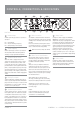
Front Panel
5
6 7
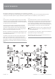
The Synergy-2 Series differ only slightly across all models and all share the same features on their front panels.
Figure 1 shows the panel layout of a SY2200 Synergy-2 amplifi er. It is similar for the SY2400, SY2700 & SY2900.
The functions of the controls and indicators are as follows:
1
4
2
3
NOTE: You should always ensure that the fan grille is kept clean and free from the build up of dust and lint.
This will ensure longer operation of your amplifi er and reduce the possibility of it prematurely going into thermal
shutdown mode. See the section “Installation - Cooling “ on page 14 for recommended cooling procedures.
6