
Specifications


OPERATION
PAGE 9SYNERGY 2 – OPERATION MANUAL
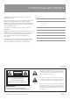
IMPORTANT: All signal source equipment should be adequately
earthed. This not only ensures your safety but everybody else’s as
well. Faults can and do occur in mains connected equipment where
the chassis can become “live” if it is not properly earthed. In these
instances, the fault in a “fl oating” (ungrounded) piece of equipment
will look for the shortest path to ground, which could possibly be your
amplifi er’s input. If the fault current is large enough, it will destroy the
input to your amplifi er and look for the next available path, which may
be you!
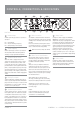
Before making any connections to your Synergy-2 Series amplifi er, observe the
following:
Ensure the mains voltage supply matches the label on the rear panel of your
amplifi er (+/- 10%).
Ensure that the power switch is OFF.
Ensure that all system grounds (earth) are connected from a common point.
Avoid powering equipment within a system from multiple power sources that
may be separated by large distances.
Check the continuity of all interconnecting leads to your amplifi er; ensure that
there are no open or short circuited conductors.
Ensure that the power handling of your load (speakers) can adequately cope
with the power output of the amplifi er.
Before operating your Synergy-2 Series amplifi er, ensure that:
- The attenuators are at the “OFF” position (fully anticlockwise).
- The GROUND LIFT Switch is not engaged (should be in the
“out” position).
- The BRIDGE Switch is not engaged if you are not running the
amp in bridged mode.
Powering Up
REMEMBER: The amplifi er should be the last piece of equipment that
you turn on and the fi rst piece of equipment that you turn off.
We recommend turning the attenuators on your amplifi er down when turning
the unit on.
When you power up your Synergy-2 Series, your amplifi er goes through an
initialising period before it will accept signal. The Inrush Current Suppression
(ICS) circuit is in operation for the fi rst 0.5 seconds. This limits the mains cur-
rent, to prevent ”nuisance-tripping” of circuit breakers.
During this period you will hear a couple of relays “click”, indicating mains is
now directly applied to the amplifi er and the signal path is connected.
While the ICS circuit operates there is also a 30dB mute on the signal input.
After two seconds this mute will release, allowing any applied signal to pass
un-attenuated.
When switching the amplifi er off, wait a couple of seconds before switching
the amplifi er on again. This allows the ICS circuit to reset.
Level Matching
The normal operating position for the attenuator is the max position (fully
clockwise, no attenuation). In this position the amplifi er operates at full gain.
Turning the attenuator back (anticlockwise) reduces the input sensitivity.
NOTE: If full power output is required, you should operate your
amplifi er with the front panel attenuator above the half way
(12o’clock) position, otherwise clipping of the input circuitry and its
resultant distortion will occur before full output power is achieved.
Sensitivity
Your amplifi er is a linear device operating with a fi xed input to output voltage
gain (less attenuation). The maximum output voltage swing is determined by
the applied mains voltage, load, load type and the duty cycle of the applied
signal.
The input sensitivity for your Synergy-2 Series amplifi er when the attenuator
is at maximum position (fully clockwise) is nominally:
+2.2dBu (1.0 volts in) for rated power into a 4 ohm load.
Each channel of your Synergy-2 Series amplifi er has a nominal balanced input
impedance of 20kOhms (@1kHz) and should not present a diffi cult load for any
signal source.
Your signal source (i.e. the equipment feeding signal to the amplifi er) should
have an output impedance of 600 Ohms or lower to avoid unwanted high
frequency loss in the cabling.
Input overload occurs at +20.5dBu(8.25volts).